
RF oscillator circuit (2N3904)
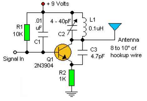
The RF oscillator circuit described is a fundamental design often used in various applications such as signal generation and testing. The circuit typically consists of a few essential components, including an oscillator stage, an output stage, and an antenna for signal transmission.
The oscillator stage is usually formed by a transistor, which can be configured in a common-emitter or common-collector arrangement, depending on the desired gain and frequency stability. The choice of transistor will influence the overall performance, but as noted, standard components can be utilized. The feedback loop is created using the inductor (L1) and a capacitor to set the oscillation frequency, which is determined by the formula f = 1 / (2π√(LC)), where L is the inductance and C is the capacitance.
In this design, the L1 antenna coil is a critical component, as it not only serves as an inductor for the oscillator but also acts as an antenna for radiating the RF signal. The construction of the coil is straightforward; by winding 8 to 10 turns of 22 gauge insulated wire around a suitable form, such as a pencil, the inductance can be adjusted by varying the number of turns or the diameter of the coil. This flexibility allows for experimentation with the oscillator's frequency, which can be observed by tuning a standard FM radio receiver to detect the emitted signal.
The coupling of the input signal to the oscillator stage is achieved using a disc capacitor of approximately 0.1µF. This capacitor serves to block any DC component while allowing the AC signal to pass through, ensuring that the oscillator can function effectively without interference from other circuit elements.
Overall, this RF oscillator circuit offers a simple yet effective platform for learning about oscillation, radio frequency transmission, and basic electronic principles. It provides an excellent opportunity for experimentation and understanding the relationship between component values and circuit behavior.This basic RF oscillator circuit is easy to build and the components are not critical. Most of them can be found in your junk parts box. The L1 antenna col can be made by close winding 8 to 10 turns of 22 gauge insulted hookup wire around 1/4 inch form such as a pencil. You can experiment with the size of the coul and the number of turns to see how it affects the frequency and signal output of the oscillator. You should be able to pick up its signal with standar FM radio receiver. The Signal In should be coupled by disc capacitor of about 0.1uF to the stage in front of it. 🔗 External reference
Related Circuits
This is a simple magnetic levitation circuit that suspends objects at a specified distance below an electromagnet. The underlying physics involves providing a magnetic force that counteracts gravity. The magnetic levitation circuit operates by utilizing an electromagnet, which generates a...
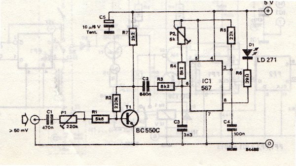
The transmitter is equipped with an LM567 tone decoder circuit. An audio signal (at least 50 mV peak-to-peak) is amplified with a transistor (T1) and then used to modulate IC1. The infrared transmitter frequency is adjusted with potentiometer P2...
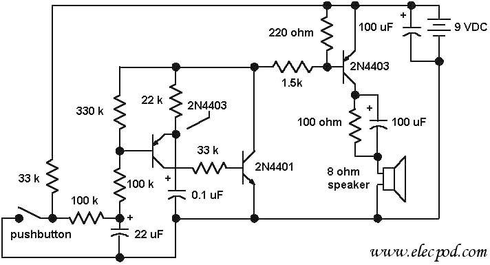
The core component of the circuit is a dual transistor flasher with frequency modulation applied to the base of the first transistor. When the pushbutton is pressed, the oscillation frequency increases to a peak, and when the button is...
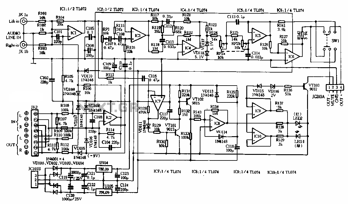
The schematic illustrates the subwoofer amplifier stage, specifically the pre-amplifier circuit and the signal processing circuit. Notably, it features two LM3886 power ICs from the American company NS, which facilitate BTL (Bridge-Tied Load) speaker operation at an 8-ohm impedance...
The ATMEL AVR programmer operates with the Windows program "Ponyprog," which is compatible with Windows 95, 98, and XP. The ATMEL AVR programmer is a device designed for programming AVR microcontrollers. It interfaces with the microcontroller through the ISP (In-System...
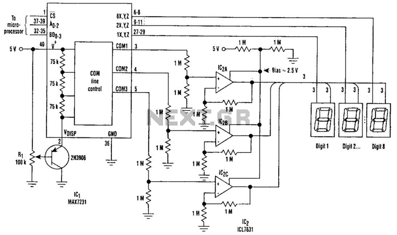
Large LCD devices with one or more displays exhibit significant driving capacitance to the driver circuits. To address this issue, the drive circuit incorporates a buffer amplifier for each of the three common lines. Each amplifier can be programmed...