
Philco 32B Farm Radio Restoration

The Philco 32B radio schematic illustrates a well-designed circuit with a focus on efficient power use in a 32-volt system. The power supply section utilizes a vibrator circuit to convert DC to high-voltage AC, which is then rectified to supply both the high voltage needed for tube operation and the filament voltage for the rectifier. The output stage employs push-pull configuration with type 42 output tubes, optimized for the 32-volt supply. The circuit topology is designed to minimize power loss while maximizing audio fidelity and reception quality across the broadcast and police/aircraft bands. The RF amplifier stage enhances signal reception, allowing the radio to effectively pick up weaker signals. Careful attention to component ratings is crucial, especially considering the potential for damage from incorrect voltage connections. The oscillator circuit's unique design, which employs the second harmonic for the police/aircraft band, showcases innovative engineering aimed at enhancing the radio's versatility. The use of a low-resistance field coil in the speaker circuit further illustrates the design's adaptability to different operational requirements. Overall, the Philco 32B represents a significant piece of historical technology, reflecting the transition from battery-operated systems to more modern electrical infrastructures in rural areas.This radio was purchased on eBay as not working, and obviously missing all tubes and tube shields. I was told that it is a relatively rare set, being a Philco and a 32 volt farm radio. Most 32 volt radios I have seen were made by Delco, Silvertone, Coronado (Wells-Gardner), Parmak, Crosley and Universal Battery Company. 32 volt radio sets were use d in rural areas before electrification. Some farms had complete 32 volt DC power systems for lamps, fans, farm machinery, appliances such as toasters, and of course radios. 32 volt house wiring, lamp sockets, and receptacles were the same as those used for today`s 120 volt AC power.
This was done because they knew that eventually they would get high-line AC power (Rural Electrification Act of 1936), and thus would not have to rewire the house! The 32 volt DC power originated from batteries, usually a bank of 16 2 volt wet cell storage batteries.
These could be charged by a motor generator set, or even by wind power (Wincharger). Many of these types of radios are found destroyed because dealers or sellers will plug them into a 120 volt socket to "test" them prior to sale. There are several types of 32 volt radios. One type uses 32 volts for the set`s high voltage supply, as well as for the filament supply for the tubes.
These types of radios typically use parallel or push-pull output tubes to overcome the low B+ supply. The RF, IF, and low level AF tubes seem quite happy with 32 volts on the plate. A commonly used output tube is the type 48, which has a 30 volt 0. 4 amp filament. These tubes are most often found burned out since they are directly across the line and someone usually has plugged the set into 120 volts in its lifetime.
Another type of 32 volt set uses a vibrator power supply like used in early car radios and in 6 volt farm radios. A vibrator chops the 32 volt DC into "AC" and a transformer steps up the voltage. The vibrator may also rectify the resulting high voltage AC, or a separate tube rectifier may be used.
The Philco 32B uses a vibrator with a separate tube rectifier. But the power supply is very large and heavy! I was really curious why. When opened up, the vibrator and transformer were massive. Looking at the schematic in Riders revealed the answer: the vibrator transformer not only supplies the high voltage, but also supplies the filament voltage for the type 84 rectifier! I have never seen such a configuration before. So I was determined to get the radio working. See for the schematic on Nostalgia Air. The Philco 32B is basically a modified Philco 89. The set has 5 tubes plus rectifier, and has an RF amplifier stage. It receives the broadcast band (520-1500 kHz) and also has a "police/aircraft" band. There is no dial scale for this band, but it was later determined that the coverage is 1300-3260 kHz.
The main differences between the Philco 32B and the 89 are: A different speaker is used which has a low-resistance field coil. This coil is used, along with an added power resistor and the pilot lamp to compensate for the difference in filament current for the type 42 output tube and the remainder of the tubes (all 300ma types).
The model 89 speaker field is the high resistance type and is used as a power supply choke. When I unpacked the radio and looked under the chassis, my heart sank: the oscillator coil was missing. Also, the wires to the volume control were all disconnected. The good news was that the remainder of the set was virtually all original. I could find only one component that had ever been replaced. Before proceeding with the restoration, I took another look at the schematic. While the radio has two bands, I noticed that the oscillator coil was NOT switched between broadcast and police.
What`s up with that After some head scratching, I finally figured out that on the police/aircraft band, the second harmonic of the oscillator is used. Since the IF frequency is 260 kHz and the broadcast 🔗 External reference
Related Circuits
The schematic illustrates a standard AM radio circuit utilizing NPN transistors. This generic circuit does not provide specific values for all components, serving instead as a reference point for experimenters to begin their projects. The schematic of a typical transistor...
Nearly all AM radio manufacturers utilized this specific circuit from approximately 1948 to 1963. There is a growing interest in collecting these radios as antiques. Credit for the creator of this figure and caption is sought, but the source...
This compact device serves as a replacement for the input transistors and related circuitry on a single TO-220 style package. A decision was made to substitute the original driver board with a newly fabricated printed circuit board (PCB) designed...
This circuit diagram represents a radio-controlled system, commonly utilized in toy car applications for children. The circuit comprises two main components: the transmitter and the receiver circuits. The transmitter circuit generates radio signals through an oscillator circuit built with...
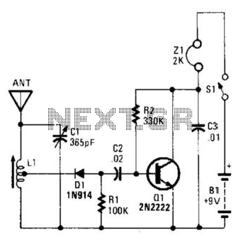
An AM radio can be constructed using a simple diode detector and an audio amplifier. A random length of wire typically serves as an antenna. LI is an adjustable ferrite loopstick similar to those used in transistor radios. An AM...
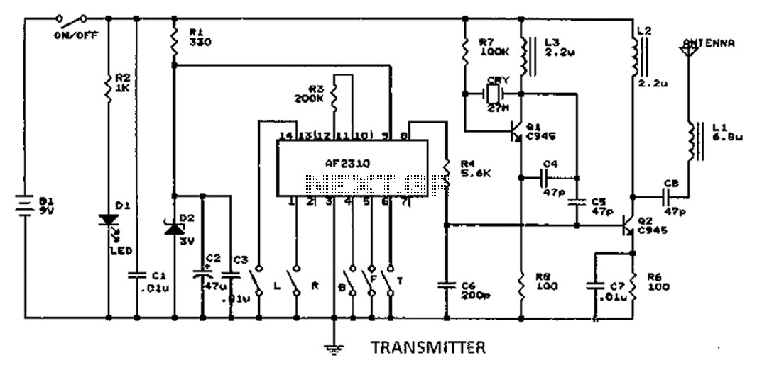
A radio control circuit designed for controlling small motors, similar to a car radio remote control toy, offers seven functions: forward, backward, left, right, left behind, right behind, and stop. The circuit requires a 27.9 megahertz frequency and a...