
TRANSISTORIZED AM RADIO
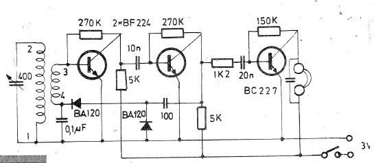
The schematic of a typical transistor AM radio circuit primarily consists of several key components: an antenna, RF amplifier, mixer, local oscillator, IF amplifier, detector, and audio amplifier. The use of NPN transistors in this design allows for efficient signal amplification and processing.
The antenna captures the radio frequency signals and feeds them into the RF amplifier, which boosts the weak signals. The amplified RF signal is then sent to the mixer, where it is combined with a signal from the local oscillator to produce an intermediate frequency (IF) signal. This mixing process is crucial for demodulating the AM signal.
The IF amplifier further amplifies the intermediate frequency signal, enhancing the quality of the audio output. The detector circuit extracts the audio information from the IF signal, converting it back into an audible format. Finally, the audio amplifier increases the volume of the detected audio signal, allowing it to be heard through speakers or headphones.
Due to the generic nature of the schematic, component values such as resistors, capacitors, and inductors are not specified. This omission is intentional, as it encourages experimenters to modify and customize the circuit based on their specific requirements and available components. For those looking to build or experiment with an AM radio circuit, the schematic serves as a foundational guide, illustrating the essential stages of signal processing in a straightforward and accessible manner.Shown is a schematic of a typical transistor AM radio. This circuit uses npn transistors. The circuit is generic; therefore, no specific values are given for some components. This circuit is for ref-erence, to serve as a starting point for experimenters.. 🔗 External reference
Related Circuits
An audible field strength indicator (AFSI) allows users to listen to variations in radio signal strength, aiding in the detection of concealed antennas. This design utilizes inexpensive and readily available components, integrating a sensitive amplified field strength detection circuit...
A solar cell radio utilizes a 3V power supply, which can be provided by either a single 3V battery or two 1.2V Ni-Cad batteries connected in series. The battery is non-removable, and the device features a mini jack socket...
Oscillating circuits (coils) are constructed on a ferrite bar. For long wave reception, winding "1-2" consists of 135 turns, while winding "3-4" has 20 turns. For medium wave reception, winding "1-2" has 75 turns, and winding "3-4" has 7...
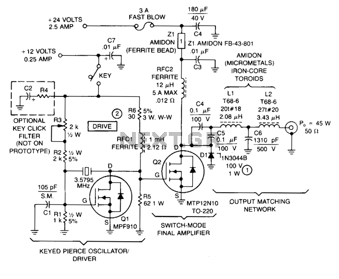
This transmitter comprises a keyed crystal oscillator/driver and a high-efficiency final amplifier, both utilizing a TMOS Power FET as the active component. The total cost of components is under $20, and no specialized construction skills or circuit boards are...

This circuit is designed for an RF (radio frequency) transmitter experiment, where a watt meter is instrumental in optimizing the transmitter circuit. A simple RF watt meter circuit is illustrated in the schematic diagram below. The circuit is not...
This circuit will filter out interference signals and ensure that the signal received from the Morse code station stands out. The described circuit functions as a signal processing system specifically designed to enhance the clarity of Morse code transmissions by...