
phone
The smart switch design leverages a PIC microcontroller, which is programmed to differentiate between standard and distinctive ringing patterns. This is crucial for users who manage multiple lines through a single telephone connection. The microcontroller continuously monitors the incoming line for ring signals, analyzing the timing of these signals to determine the appropriate response.
The detection mechanism is based on a time measurement algorithm that effectively distinguishes between the two ringing cadences. The normal ring pattern, with longer durations, is easily identifiable, while the distinctive ring requires precise timing to ensure correct routing. The decision-making process begins after the first ring is ignored, ensuring that transient noise or false signals do not trigger an erroneous relay action.
The system's reliability is enhanced by the requirement for two rings before a decision is made. This feature is particularly beneficial for users with answering machines, allowing them to set their devices to respond only after a specific number of rings, thus preventing premature activation.
The relay's operation is straightforward: upon identifying the type of ring, the microcontroller commands the relay to switch to the appropriate output line. This allows the call to be routed to the correct device, whether it is a phone or an answering machine. The relay maintains its state until the next ringing event, ensuring minimal disruption to ongoing calls.
The assembly code provided with the design outlines the initialization and operational logic of the microcontroller. It includes provisions for setting up the clock source and configuring the input and output ports. The time_check subroutine plays a critical role in ensuring that the timing measurements are accurate, which is essential for the reliable operation of the switch.
In summary, this smart switch design provides a robust solution for managing multiple phone numbers over a single line, utilizing a microcontroller to intelligently route calls based on distinctive ringing patterns. The combination of time measurement, relay control, and programmable logic results in a versatile and effective telephone management system.Distinctive ringing lets phone service customers have two phone numbers with only one twisted-pair line. The standard ring cadence tells the customer that someone is calling on number X, while the distinctive ring cadence tells him (her) that someone is calling on number Y.
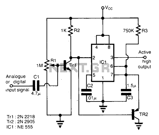
People can easily tell which ring is which. But equipment like answering m achines can`t. Here is the complete design of a smart switch, based on a PIC (Microchip Technology, Inc. , 2355 West Chandler Blvd. , Chandler, AZ) microcontroller, that will detect the ring and route the call appropriately. The schematic is shown in figure 1. The assembly code (contact us if you would like a text file of the code) follows the figure. The Data Access Arrangement shown is intended for registration in the United States and Canada. A normal ring is 2 seconds ON and 4 seconds OFF. Distinctive ringing has 1 second ON, 0. 75 second OFF, 1 second ON, and 4 seconds OFF. Therefore, if a ring is ON for more than 1 second, it is normal. The switch works by measuring time intervals. For reliable operation, the switch ignores the first ring and begins its measurements on the second one. The incoming line is always connected to one or the other of the output lines. Once a decision is made and the relay is opened or closed, it is simply left in this state until the next ring cadence.
On power up the relay is open. Because the switch requires at least two rings before it can make a decision, connected devices such as answering machines should be programmed to require 4 rings. ;The ring detector has one phone line input and two outputs. It ;switches the input to one of the two outputs based on which type ;of ringing is present. When ringing stops it leaves the relay in ;the last position used. ;Normal ringing consists of 2 second of ring followed by 4 second ;silence. Distinctive ring is 1 sec. ring, 3/4 second gap, 1 second ;ring, and 4 second silence. ;The algorithm is as follows: ; start ; wait for ring ; check if valid ; if not, go to start ; wait for end of ring.
; measure next ring. ; if longer than 1. 5 sec goto line1 ; else goto line2 ; line1 ; switch relay to line 1 (normal ring) ; goto start ; line2 ; switch relay to line 2 (distinctive ring) ; wait for ring to stop ; goto start ;option register values. rts equ 0x20 ;set for external clock. rte equ 0 ;increm on low-to-high. psa equ 0 ;prescale rtcc. ps2 equ 0 ;prescale value = 16. This gives a ps1 equ 2 ;clock period of 21. 8 msec. to rtcc. ps0 equ 1 option_val equ rts | rte | psa | ps2 | ps1 | ps0 ;set up the output port. bcf o_start, test ;it is done in this way to avoid bcf o_start, relay ;problems associated with ;port being an input port until ;execution of the "tris" movfw o_start ;instruction.
movwf outport clrw tris outport time_check ;subroutine checks whether rtcc is 0. use zero flag ;to check. clrwdt ;kick dog. movf rtcc, w andlw 0xff ;test for zero. if rtcc was ;zero, zero flag is set. retlw 0 ;return. 🔗 External reference
Related Circuits
The circuit is designed for speech activity detection in telephone lines. This detection is particularly beneficial for half-duplex conversations between two stations, for simultaneous transmission of voice and data over the same pair of cables by interspersing data within...
Have you ever imagined controlling your home appliances using your cell phone? Numerous circuits exist for this application, typically utilizing a telephone. This circuit has been modified and redesigned for compatibility with a standard cell phone headphone jack. To...
This unit would be mounted in a small plastic or preferably metal box, with a 9V battery, level control, a male XLR connector (same as on a mic) and a switch. Current drain is low, since the circuit only...
With this circuit mounted in or near every phone in the house, it will allow users to know if the phone is being used and not to pick up the phone. When a phone is taken off hook, the...
A circuit for an offline telephone tester that does not require a telephone line for testing a telephone instrument. The circuit is simple enough to be assembled by a novice with minimal electronics knowledge. A telephone line can be...
Can be directly connected to CD players, tuners and tape recorders. Tested with several headphone models of different impedance: 32, 100, 245, 300, 600 & 2000 Ohms. Schematic shows left channel only. B1, SW1, J1 & C3 are common...