
Off Line Telephone Tester
The offline telephone tester circuit is designed to evaluate the functionality of telephone instruments without the need for an active telephone line. The main components include two transformers, several diodes for rectification, capacitors for smoothing and filtering, a push-to-on switch for activating the ringer function, and a music IC for audio testing.
The circuit utilizes a step-down transformer (X1) to convert AC mains voltage to a lower DC voltage. The dual full-wave rectifier setup allows for efficient conversion of the AC voltage into a usable DC voltage for the telephone instrument. The first rectifier circuit, composed of diodes D1 and D2, provides the necessary voltage for the telephone instrument's operation, while the second rectifier circuit (D3 and D4) ensures that the audio signals are processed correctly.
The rotary switch (S2) facilitates the selection between different testing modes, including ringer testing and audio testing. The connection to a 32-ohm headset via socket SK1 allows for real-time audio monitoring. The inclusion of a choke prevents unwanted AC signals from interfering with the audio output.
During testing, it is crucial to follow the outlined procedures to ensure accurate results and avoid damage to the circuit components. The circuit's design allows for easy assembly on veroboard, making it accessible for individuals with limited electronics experience. The layout considerations, such as the positioning of the transformers and the arrangement of switches and sockets, contribute to effective operation and ease of use. Overall, this offline telephone tester circuit is a practical tool for diagnosing telephone instruments, ensuring they function correctly without the need for an external telephone line.A circuit of an off-line telephone tester which does not require any telephone line for testing a telephone instrument. The circuit is so simple that it can be easily assembled even by a novice having very little knowledge of electronics.
A telephone line may be considered to be a source of some 50 volts DC with a source impedance of about 1 kilo-ohm. During ringing, in place of DC, an AC voltage of 70 to 80 volts (at 17 to 25 Hz) is present across the telephone line. When the subscriber lifts the handset, the same is sensed by the telephone exchange and the ringing AC voltage is disconnected and DC is reconnected to the line.
Lifting of the handset from the telephone cradle results in shunting of the line`s two wires by low impedance of the telephone instrument. As a result, 50V DC level drops to about 12 volts across the telephone instrument. During conversation, the audio gets superimposed on this DC voltage. Since any DC supply can be used for testing a telephone instrument, the same is derived here from AC mains using step-down transformer X1.
Middle point of the transformer`s secondary has been used as common for the two full-wave rectifiers ”one comprising diodes D1 and D2 together with smoothing capacitor C1 and the other formed by diodes D3 and D4 along with filter capacitor C2. The former supplies about 12 volts for the telephone instrument through primary of transformer X2 which thus simulates a source impedance, and a choke which blocks AC audio signals present in the secondary of transformer X2.
The AF signal available in secondary of X2 is sufficiently strong to directly drive a 32-ohm headset which is connected to the circuit through headphone socket SK1 via rotary switch S2. During ringing, a pulsating DC voltage from transformer X1 via rectifier diode D5, push-to-on switch S3, and contact B` of rotary switch S2 is applied across secondary of transformer X2.
The boosted voltage available across primary of transformer X2 is sufficient to drive the ringer in the telephone instrument. Please avoid pressing of switch S3 for more than a few seconds at a time to prevent damage to the circuit due to high voltage across primary of transformer X2.
The circuit also incorporates a music IC (UM66) whose output is connected to secondary of transformer X2 via switch S2 after suitably boosting its output with the help of darlington transistor pair T1 and T2. This output can be used to test the audio section of any telephone instrument. After having assembled the circuit satisfactorily, the following procedure may be followed for testing a telephone instrument.
2. To test the ringer portion, flip switch S2 to position B` and press S3 for a moment. You should hear the ring in case the ringer circuit of the telephone under test is working. Please ensure that handset is on cradle during this test. 3. For testing the audio section, flip switch S1 to position C` and connect a headphone to socket SK1. Pick the telephone handset and speak into its microphone. If audio section is working satisfactorily, you should be able to hear your speach via the headphone. If you dial a number, you should be able to hear the pulse clicks or pulse tone in the headphone, depending on whether the telephone under test is functioning in pulse or tone mode.
If the telephone under test has a built-in musical hold facility, on pressing the hold` button you should be able to hear the music. Now flip switch S2 to position A`. You should be able to hear music generated by IC1 through earpiece of the handset of the telephone under test, indicating propor functioning of the AF amplifier section.
The circuit can be assembled on a small piece of veroboard. Try to mount the two transformers on opposite sides of the board, displaced by 90 degrees. Always keep handy multi-type modular plugs for testing various types of telephones. Mount all switches, sockets and LEDs on the front of testing pan 🔗 External reference
Related Circuits
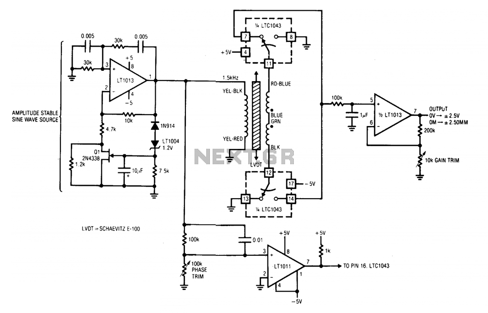
A1 and its associated components provide an amplitude-stable sine wave source. The positive feedback path utilizes a Wien bridge, tuned to 1.5 kHz. The LT1004 reference and additional components in A1's negative feedback loop stabilize the amplifier at unity...
In this auto shut-off tone generator project, connecting the switch to the 9V power supply triggers an alarm that emits a frequency of approximately 1.27 kHz. The alarm remains active for about 170 seconds (or 2.8 minutes) before it...
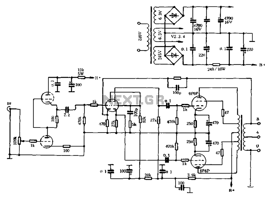
The self-generated bias amplifier tube is designed for each tube individually to alleviate the challenges faced by amateur conditions in paired amplifiers. It includes a separate DC filament power supply, which minimizes the risk of induced cross-linking and enhances...
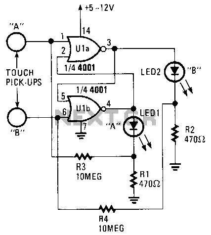
Only one LED can be illuminated when the circuit is at rest. The illuminated LED is determined by the touch pick-up that last had human contact. Pickup terminal A controls the on condition of LED1, while terminal B controls...
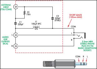
This document presents a concept for a low-cost adapter that enables the connection of a portable FM radio or MP3 player with an FM tuner to an external antenna and audio equipment, such as a hi-fi system or PC...
Using an old moving coil instrument, it is easy to create a simple voltmeter that indicates the status of a telephone line at a glance. The circuit's high input impedance allows it to be permanently connected to the line,...
Warning: include(partials/cookie-banner.php): Failed to open stream: Permission denied in /var/www/html/nextgr/view-circuit.php on line 713
Warning: include(): Failed opening 'partials/cookie-banner.php' for inclusion (include_path='.:/usr/share/php') in /var/www/html/nextgr/view-circuit.php on line 713