
Phone In Use Electronics Project
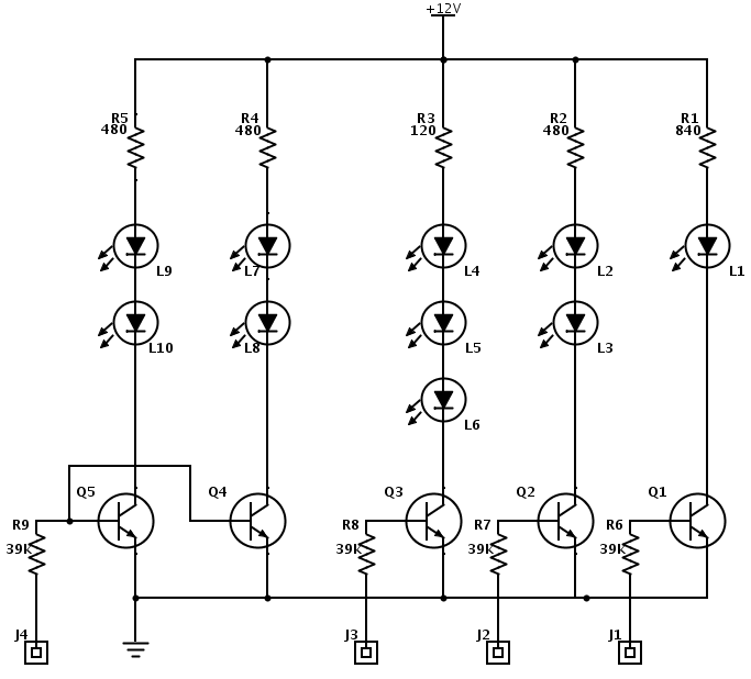
The Phone In Use Indicator is an electronic project designed to visually indicate when a telephone line is active. This circuit employs a combination of resistors, NPN transistors, diodes, and light-emitting diodes (LEDs) to achieve its functionality.
The circuit typically consists of five resistors, which are used to limit current and set appropriate voltage levels for the components. The two NPN transistors serve as switches that are triggered by the voltage changes on the phone line when the phone is in use. When the phone is picked up, the voltage drop across the line activates the first NPN transistor, which in turn activates the second transistor.
The four diodes are arranged in a configuration that protects the circuit from reverse polarity and ensures that the current flows in the correct direction. This arrangement prevents damage to the transistors and LEDs during operation. The diodes also help in isolating the phone line from the circuit, ensuring that the indicator does not interfere with the telephone's functionality.
The two light-emitting diodes serve as visual indicators. When the phone is in use, the transistors allow current to flow through the LEDs, causing them to light up. This provides a clear visual indication that the phone line is engaged, which can be particularly useful in shared environments or offices where multiple users may be using the same line.
Overall, this Phone In Use Indicator project is a practical application of basic electronic components, illustrating how simple circuitry can be utilized to provide useful functionality in everyday scenarios.Phone In Use Indicator Electronics Project using 5 resistors, 2 NPN transistors, 4 diodes and 2 light emitting diodes 🔗 External reference
Related Circuits
The microphone preamplifier circuit design presented in this schematic utilizes the SSM2015 component manufactured by Precision Monolithics Inc. (PMI). This component provides high amplification with low noise characteristics (1.3nV/f). The design is configured to handle differential input signals and...
It is illegal to create a permanent physical connection to telephone lines in certain countries, including the UK and Ireland. When constructing this circuit, it is advisable to utilize a plug-in cord to allow for disconnection in the event...
An IDE interface board is currently being developed, along with driver software to support reading and writing on a hard drive under the OS-X 2.0 RTOS. An assembled IDE interface board is available for reference. The PCB layout files...
Mobile phone battery chargers available in local markets can be quite expensive. The circuit presented here offers a low-cost alternative for charging cellular phone batteries or battery packs with a rating of 7.2 volts. This low-cost phone battery charger circuit...
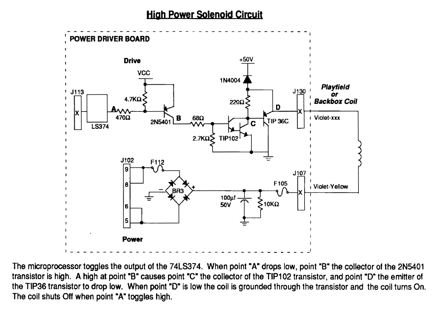
Instructions for using an LED-Wiz to control pinball solenoids. Rottendog Amusements manufactures modern replacement driver boards, such as the Williams WPC89/WPC-S replacement. Although this board is an improvement over the originals, it remains relatively large and is capable of...
This electronics project involves modifying an old radio into an iPhone dock. Video and pictures are included to illustrate the entire process. The project entails the conversion of a vintage radio device into a functional docking station for an iPhone....