
Phone line FM transmitter

The circuit operates by utilizing the existing telephone line voltage to power its components, thereby eliminating the need for external power sources. The automatic switching section is critical for ensuring that the circuit only activates when the telephone is in use. The voltage divider formed by resistors R1 and VR1 allows for fine-tuning of the activation threshold. The zener diode D2 plays a crucial role in maintaining the stability of the circuit by providing a reference voltage that governs the operation of transistor T1. When the telephone handset is lifted, the voltage drop across the line triggers the switching mechanism, allowing the circuit to transition into the active state.
In the FM transmitter section, transistor T3 is configured as a common-emitter oscillator, generating an RF signal that is modulated by the audio signals from the telephone line. The coil L1 serves as part of the oscillator circuit, determining the frequency of operation. The modulated RF signal is then transmitted via an antenna, allowing for remote listening. The design is compact, making it suitable for integration into existing telephone infrastructure without significant alterations.
To ensure reliable operation, the addition of resistor R5 and capacitor C6 addresses issues related to engagement tones during testing. This modification helps stabilize the circuit and prevents interference from affecting the normal operation of the telephone line. The overall design exemplifies a practical application of low-power electronics in telecommunications, demonstrating the potential for innovative solutions in audio transmission and monitoring.Here is a simple yet very useful circuit which can be used to eavesdrop on a telephone conversation. The circuit can also be used as a wireless telephone amplifier. One important feature of this circuit is that the circuit derives its power directly from the active telephone lines, and thus avoids use of any external battery or other power supplies. This not only saves a lot of space but also money. It consumes very low current from telephone lines without disturbing its performance. The circuit is very tiny and can be built using a single-IC type veroboard that can be easily fitted inside a telephone connection box of 3.75 cm x 5 cm.
The circuit consists of two sections, namely, automatic switching section and FM transmitter section. Automatic switching section comprises resistors R1 to R3, preset VR1, transistors T1 and T2, zener D2, and diode D1. Resistor R1, along with preset VR1, works as a voltage divider. When voltage across the telephone lines is 48V DC, the voltage available at wiper of preset VR1 ranges from 0 to 32V (adjustable).
The switching voltage of the circuit depends on zener breakdown voltage (here 24V) and switching voltage of the transistor T1 (0.7V). Thus, if we adjust preset VR1 to get over 24.7 volts, it will cause the zener to breakdown and transistor T1 to conduct.
As a result collector of transistor T1 will get pulled towards negative supply, to cut off transistor T2. At this stage, if you lift the handset of the telephone, the line voltage drops to about 11V and transistor T1 is cut off.
As a result, transistor T2 gets forward biased through resistor R2, to provide a DC path for transistor T3 used in the following FM transmitter section. The low-power FM transmitter section comprises oscillator transistor T3, coil L1, and a few other components.
Transistor T3 works as a common-emitter RF oscillator, with transistor T2 serving as an electronic on/off switch. The audio signal available across the telephone lines automatically modulates oscillator frequency via transistor T2 along with its series biasing resistor R3.
The modulated RF signal is fed to the antenna. The telephone conversation can be heard on an FM receiver remotely when it is tuned to FM transmitter frequency. Lab Note: During testing of the circuit it was observed that the telephone used was giving an engaged tone when dialed by any subscriber.
Addition of resistor R5 and capacitor C6 was found necessary for rectification of the fault. 🔗 External reference
Related Circuits
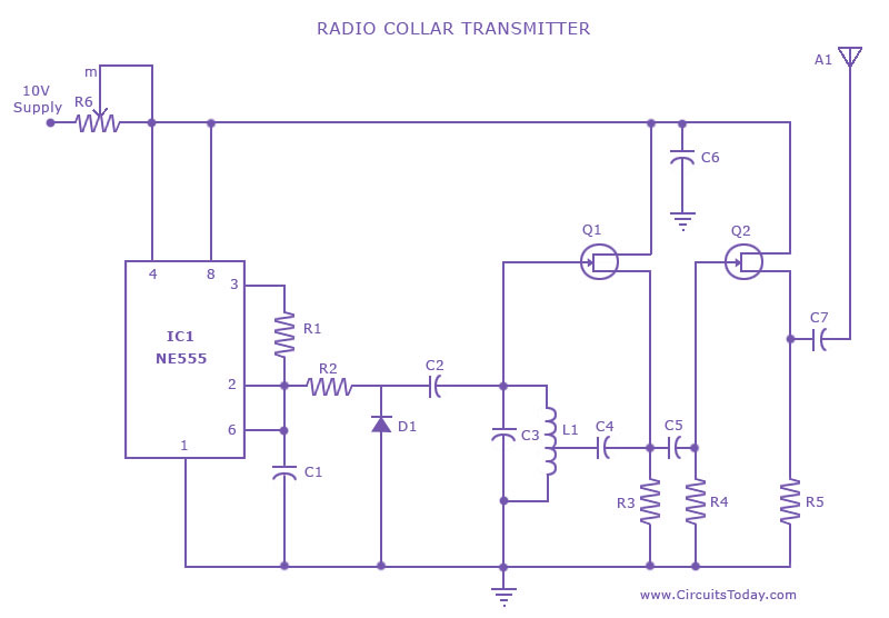
This is a radio transmitter circuit diagram designed for integration into radio collars using the NE 555 integrated circuit. The circuit transmits a pulse in the FM band, specifically between 88 MHz and 105 MHz. The radio transmitter circuit utilizes...
The primary configuration of the circuit consists of a Colpitts type oscillator. Components C3, C4, C5, C6, CD1, CD2, and L1 determine the operational frequency. The BF982 and a dual gate MOSFET serve as the active elements in the...
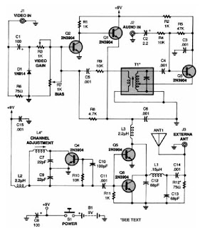
A low-power VHF TV transmitter is an essential tool for video enthusiasts, allowing the transmission of signals from a VCR to any television in a home or backyard setting. This device enables the convenience of watching movies by the...
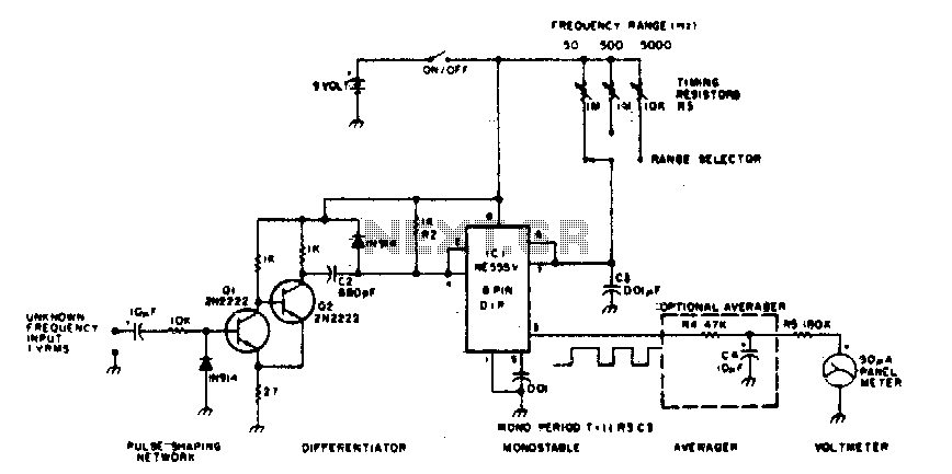
The 555 timer is utilized in a monostable multivibrator circuit that generates a pulse of fixed time width, which is activated by an unknown input frequency. The 555 timer in a monostable configuration operates by producing a single output pulse...
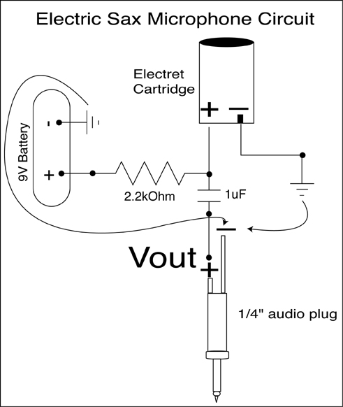
A condenser microphone (electret type with two terminals) is to be powered. A resistor of 1 kΩ and a capacitor of 10 µF have been connected to its positive terminal, while the other terminal is grounded. To power an electret...
This document presents a schematic diagram of an electret microphone pre-amplifier utilizing the LMV721 operational amplifier. The LMV721 is chosen for its low noise and low power characteristics. The electret microphone pre-amplifier circuit is designed to amplify the weak audio...