
Using LEDs as colour sensors
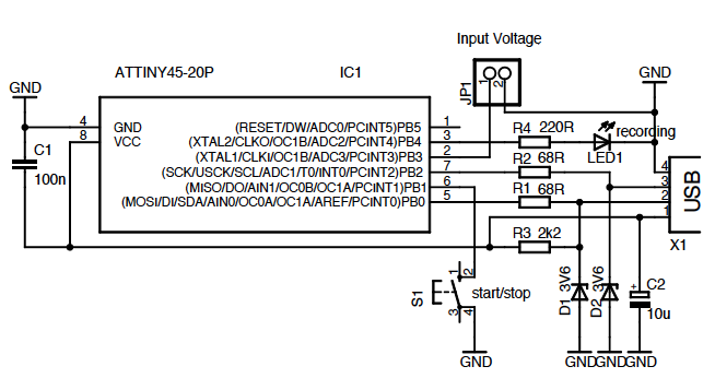
The circuit operates by utilizing a reversed LED as a light sensor, which generates a small analog voltage proportional to the intensity of light it receives. This analog signal is then processed by an operational amplifier (op-amp) configured to amplify the signal to a suitable level for digital conversion. The op-amp's gain can be adjusted to ensure that the output voltage is within the acceptable range for the subsequent digital processing stage.
The digital conversion is achieved through a comparator circuit, which compares the amplified analog signal against a predefined threshold voltage. When the analog signal exceeds this threshold, the comparator outputs a high digital signal (logic '1'); otherwise, it outputs a low digital signal (logic '0'). This on/off output can be used for various applications, such as triggering a microcontroller or activating other digital logic circuits.
The modified schematic simplifies the original design by reducing the number of components and focusing on the essential functions required for analog-to-digital conversion. This streamlined approach enhances reliability and efficiency, making it more suitable for practical applications.
The hesitation to use the LED as a color sensor stems from previous testing results that may not have met the desired performance criteria. Alternative sensing methods or components might be considered to achieve more accurate color detection, such as photodiodes or specialized color sensors that offer improved sensitivity and spectral response.Part of this circuit is turning the analog signal coming from the reversed LED (sensing mode) and amplified by the op amp into a digital (on/off) signal. I got rid of all that. This is the modified simplified version of the schematics: Another possibility is the one explored in this tutorial but given my results so far I`m discouraged to use LED as colour sensors:
🔗 External reference
Related Circuits
A wide range frequency meter is a useful tool for an electronics lab. This project describes a frequency meter based on the AT90S231 microcontroller that can measure input frequencies up to 50 MHz. The measured frequency is displayed on...
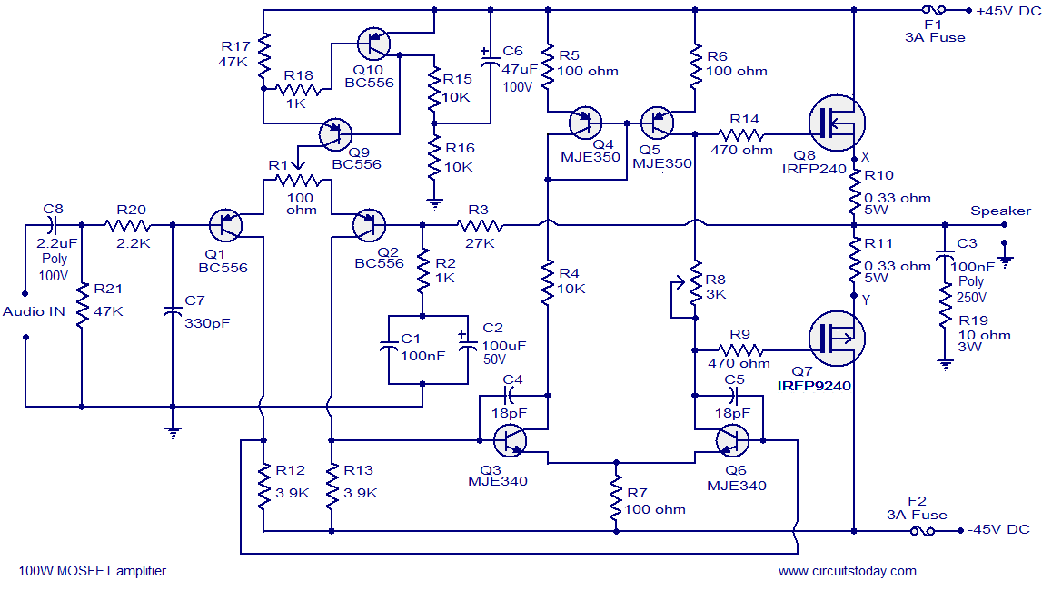
Hi-fi 100W MOSFET power amplifier circuit. Operates from a 45V dual supply. Delivers 100W to an 8-ohm speaker and 160W to a 4-ohm speaker, with low distortion. The Hi-fi 100W MOSFET power amplifier circuit is designed to provide high-quality audio...
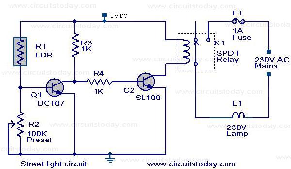
The circuit diagram of an Automatic Street Light Controller Circuit is explained in this post. The Automatic Street Light Controller Circuit is designed to automatically turn on street lights at dusk and turn them off at dawn. This functionality is...
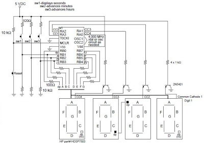
A digital clock project utilizing the PIC16C54 microcontroller can be constructed using the provided circuit diagram. This electronic project features a straightforward time-of-day clock that includes four seven-segment LED displays and three input switches, along with an additional reset...

The super dimmer is an improved version compared to the standard dimmer currently in use. Testing its performance will provide a clearer understanding of its advantages. The super dimmer operates using advanced technology that allows for finer control over...
The voltage to frequency converter (V/FC - VCO) circuit consists of a UJT (uni-junction transistor) oscillator in which the timing charge capacitor C2 is utilized. The voltage to frequency converter circuit operates by converting an input voltage into an output...