
Phono RIAA Preamplifier
This circuit represents an advanced design proposal for a RIAA preamplifier, which is crucial for amplifying the low-level signals from a phono cartridge to line level. The design consists of two main stages: an initial discrete component stage followed by an operational amplifier stage, denoted as IC1. The operational amplifier is employed in the negative feedback loop, which is essential for implementing the RIAA equalization curve necessary for accurate audio playback.
Key components in the circuit include capacitors C2 and C15, which must be selected based on the specifications of the phono cartridge being used. These capacitors play a vital role in shaping the frequency response of the preamplifier and must be chosen to match the output impedance and characteristics of the cartridge.
Transistors Q1, Q2, Q8, and Q9 are critical in the design, and it is recommended that they are selected for their matched characteristics. This matching is important for maintaining thermal stability and ensuring that the transistors behave similarly under varying conditions. A hFE meter can be used to measure and select pairs of transistors with similar gain characteristics, which will enhance the performance of the differential amplifiers.
Trimmers TR1 and TR2 are incorporated to adjust the input differential amplifier characteristics, allowing for the nulling of any DC offset voltage at the output of this stage. This adjustment is crucial for maintaining signal integrity and preventing unwanted distortion in the audio signal.
Capacitors C4 through C17 and C11 through C24 should be matched in capacitance to minimize variations that could affect the performance of the circuit. Using a capacitance meter to ensure these components have identical values can eliminate the need for purchasing precision capacitors, thereby reducing costs while maintaining performance.
All resistors in the circuit should be metal film with a tolerance of 1%. This specification ensures low noise and high accuracy in the signal path, which is essential for high-fidelity audio applications.
The power supply for this preamplifier can be derived from an existing amplifier or an external stabilized supply, providing ±15V at 100mA. This voltage level is standard for operational amplifier circuits and ensures adequate headroom for the audio signals while maintaining low distortion levels.In this circuit exists a second designing proposal of preamplifier RIAA. The first stage uses discernible components and in second exist a opamp. [IC1]. In the negative feedback exist the correction RIAA filters. Certain points need certain discriminators: 1] capacitors C2 and C15, will be supposed to suit with the cartridge characteristics that you will use. 2] Transistors Q1-2 and Q8-9, good is they have matched in their characteristics and they are found very near so that they have the same thermic behavior.
This can become with choice from a lot of transistors so that we find certain pairs with same characteristics, measuring with a hfe meter. 3] the trjmmer TR1-2 regulate the characteristics of differential amplifiers in the input, for null of DC voltage in the exit of stage.
4] the capacitors C4-17 and C11-24 should matched between them with capacitance meter, so that they have the same values, avoiding in this way the purchase of precise capacitors. 5] All the resistors should be metal film 1%. the circuit supply become from power supply, that exist already in amplifier or from external good stabilised supply ± 15V 100mA.
🔗 External reference
Related Circuits
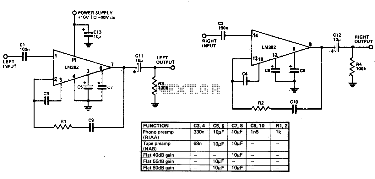
Limited information is available regarding the operation of the LM382, as the majority of its circuitry is integrated within the IC. Most components responsible for frequency determination are located on the chip, with only capacitors being externally mounted. The...
This project originated as an effort to create an inexpensive phono stage for an old turntable equipped with a low-cost cartridge using available components. However, it evolved into a noteworthy project that significantly enhances the overall analog setup. The...
Low-noise preamplifier circuit. This circuit demonstrates a typical low-noise preamplifier design, which can be utilized to amplify signals from sources such as magnetic heads and microphones within audio applications. The input signal is coupled through a capacitor and subsequently...
This circuit is primarily designed to provide a microphone input for standard home stereo amplifiers. Utilizing a battery supply minimizes the risk of low-frequency hum interference from mains power, simplifying the connection to the amplifier by eliminating the need...
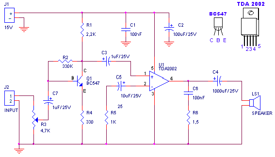
A small amplifier with nice characteristics: Tendency of catering: 15V. Force of expense: 4.2Wrms in the 4W. Minimal signal of entry: 94mVp-p with preamplifier, 0.65Vp-p without the preamplifier. More: Materially: R1=2.2kΩ R2=330kΩ R3=4.7kΩ logarithmic potentiometer R4=330Ω R5=1kΩ R6=1.5Ω C1,...
To listen to old vinyl LPs with proper sound quality using a dynamic cartridge, a circuit known as an RIAA corrector is required. This circuit is commonly found in older amplifiers but is not typically included in modern home...