
Photo alarm
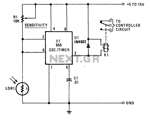
The circuit can be modified by placing relay K1 and diode D1 between pin 3 and ground. In this configuration, the relay deactivates when the voltage on pins 2 and 6 exceeds 0.5 Vcc and activates when it falls below 0.5 Vcc. This modification is beneficial when the relay has single-throw contacts. The opening and closing of the relay contacts occur at different illumination levels, establishing a hysteresis of 1/3 Vcc. This hysteresis is advantageous as it prevents the circuit from oscillating and the relay from chattering in response to minor variations in illumination.
LDR1 serves as a critical component in light-sensitive applications, effectively translating light intensity into a varying resistance value that influences the operation of the relay. The voltage divider configuration allows for precise control of the relay activation threshold based on ambient light conditions. The sensitivity control resistor R1 provides an adjustable parameter that enables the user to set the desired light level at which the relay should activate or deactivate, accommodating various operational scenarios.
The incorporation of hysteresis through the relay modification enhances the stability of the circuit, ensuring that transient changes in light do not lead to rapid on-off cycling of the relay. This stability is essential in applications where consistent relay operation is required, such as in automatic lighting systems or alarm circuits triggered by light levels. The use of a diode in conjunction with the relay also serves to protect the circuit from voltage spikes caused by the inductive load of the relay coil, thus enhancing the overall reliability of the design.
In summary, the described circuit effectively utilizes an LDR in conjunction with a relay to create a light-sensitive switching mechanism, with options for modification to improve performance and reliability in various applications.LDR1, a cadmium sulphide (CDS) photoresistive cell is used as the lower leg of a voltage divider between Vcc and ground. The timer terminals 2 and 6 are connected to the junction of the photocell and SENSITIVITY control Rl.
The resistance of the photoresistive cell varies inversely as the light intensity; resistance is high when the illumination level is low; low in bright light. (The Radio Shack CDS cell 276-116 has a typically wide resistance range—about 3 megohms in darkness and 100 ohms in bright light.) When the light is interrupted or falls below a level set by SENSITIVITY control Rl, the rise in LDRl's resistance causes the voltage on pins 2 and 6 to rise.
If the control is set so the voltage rises above 2A Vcc, the relay pulls in. The relay drops out when the light level increases and the drop across the photocell Ms below lA Vcc. (The circuit can be modified by placing relay K1 and diodeD1 between pin 3 and ground. In this case, the relay drops out when the voltage on pins 2 and 6 rises above V% Vcc, and pulls in when it falls below Vi Vcc. This modification is valuable when the relay has single-throw contacts.) Opening and dosing of the relay contacts occurs at different illumination levels.
This J/3 Vcc hysteresis is an advantage that prevents the circuit from hunting and the relay from chattering when there are very small changes in illumination. 🔗 External reference
Related Circuits
This PC Watcher circuit is designed to prevent unauthorized access to personal computers. After being constructed on a small piece of veroboard, it can effectively enhance security. The PC Watcher circuit operates by monitoring the status of the computer and...
The following circuit illustrates photovoltaic light sensors in a solar tracker. Features include accuracy, low cost, simplicity, and a single-axis electronic design. The photovoltaic light sensor circuit is designed to optimize the alignment of solar panels with respect to the...
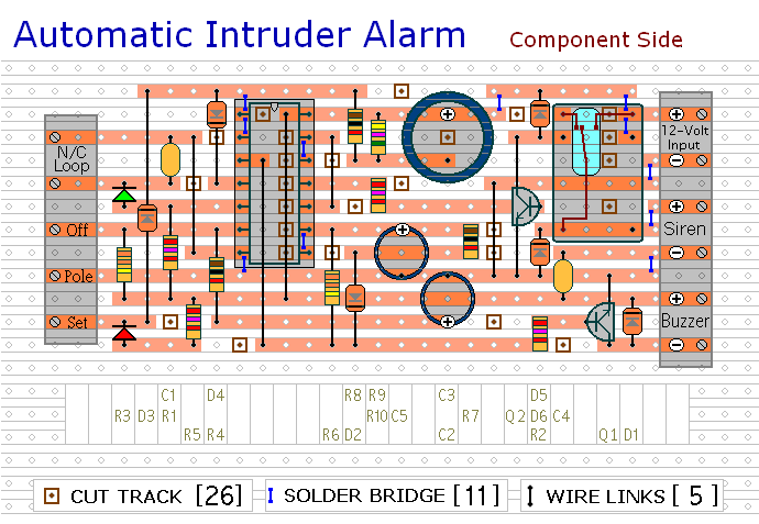
This circuit includes automatic exit and entry delays, a timed bell cut-off, and a system reset feature. It is designed to work with standard normally-closed input devices such as magnetic reed contacts, micro switches, foil tape, and passive infrared...
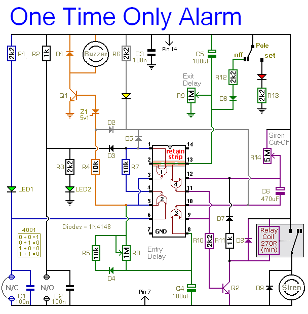
When this alarm is activated, its siren will sound once for up to 20 minutes. After this period, it will switch off and remain off. The basic circuit features a single zone with independently adjustable exit and entry delays,...
The ultra-simple tilt sensor alarm circuit can be constructed using readily available, inexpensive components. This circuit is based entirely on transistor technology. The homemade tilt sensor consists of a small glass or plastic bottle with two metal needles inserted...
To increase the chances of observing the northern lights, the limitations of current aurora prediction methods can be circumvented by directly sensing the light emitted by the aurora. The Aurora Alarm is a device designed to achieve this goal...