
Tilt Sensor Alarm Circuit

The tilt sensor alarm circuit operates on the principle of using a simple tilt switch mechanism, which is effectively created by the arrangement of the metal needles and water within the bottle. When the tilt sensor is in a neutral position, the water does not bridge the gap between the needles, and thus, no current flows to the base of transistor T1, keeping the circuit in an inactive state. Upon tilting the device, the water shifts and creates a conductive path between the needles, applying a positive voltage to the base of T1.
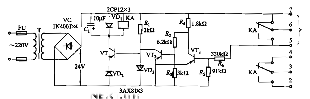
Transistor T1 is configured as a switch that controls the next stages of the circuit. Once T1 is activated, it allows current to flow through T2, which serves a dual purpose: it not only activates T1 but also provides a stable bias to maintain its active state, effectively latching the circuit. The activation of T2 then leads to the activation of T3, which is responsible for triggering the silicon-controlled rectifier (SCR) T4. The SCR acts as a switch that can handle higher currents and is used to drive the piezo sounder (BZ1).
The piezo sounder produces an audible alarm when the SCR is triggered, indicating that the tilt sensor has been activated. To reset the system, the user can press the power/reset switch S1, which interrupts the current flow and returns the circuit to its inactive state. The inclusion of a preset potentiometer (P1) allows for fine-tuning of the sensitivity of the tilt sensor, accommodating variations in sensor design or environmental conditions.
The optional resistor R3 can be included to limit the current through the piezo sounder, depending on its specifications. The circuit is designed to be flexible, allowing for the substitution of components such as the SCR and the piezo sounder with equivalent parts that meet the necessary electrical characteristics. This design is practical for simple applications where a basic alarm system is required, and it demonstrates the effectiveness of using transistors in alarm circuits.Ultra simple circuit of the tilt sensor alarm presented here can be fabricated using readily available inexpensive components. The circuit is a true transistor based design. Home made Tilt sensor for this circuit is an ordinary little glass/plastic bottle with two metal needles inserted through its cap, and a small quantity of water inside.
Usually, transistor T1 is in inactive state. When the sensor assembly is tilted, both needles inside the sensor (bottle) are short circuited by the water and a positive voltage is available at the base of T1 and it becomes active. Activation of T1 causes the activation of next transistors T2 and T3. After this, T2 supplies constant bias for T1 to make it latched and T3 triggers the SCR(T4) which inturn energises the active piezo-sounder(BZ1).
Once activated the circuit can be deactivated by depressing the power/reset switch S1. Preset pot P1 is deliberately added here to adjust the circuit sensitivity. This may become necessary if you are trying a different (readymade) tilt sensor. Similarly, SCR(T4) and piezosounder (BZ1) may be replaced with near equivalent parts. Resistor R3 (100-150 Ohm) is optional. Thanks to Mr. Colin Mitchell for his feedback. My prototype was tested with this home-brewed tilt switch . But it is always better to use a ready-made tilt switch. 🔗 External reference
Related Circuits
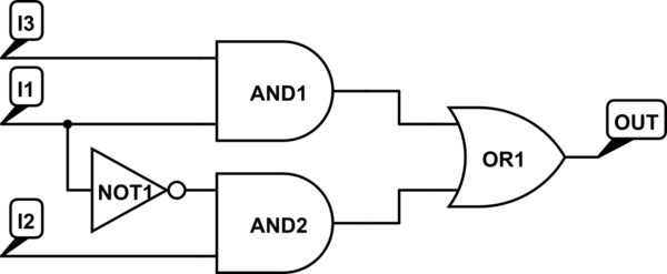
There are integrated circuits that contain AND, OR, and NOT gates. The inquiry revolves around the existence of a single chip that encompasses all the required logic gates. If such a chip does not exist, specific alternatives should be...
This AC drill speed controller circuit schematic allows for the control of the drilling speed of a borer or drilling machine. This project is based on the principle that... The AC drill speed controller circuit is designed to modulate the...
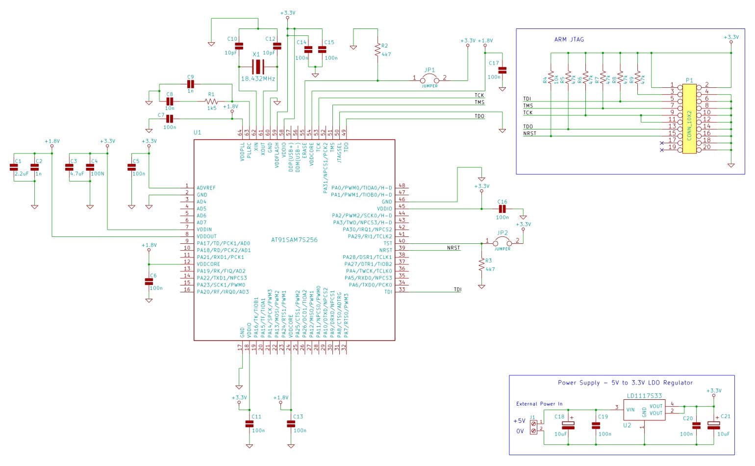
The minimum number of supporting components required to build a circuit using AT91SAM7S microcontrollers. This example uses the AT91SAM7S256 ARM7 microcontroller. To construct a circuit utilizing the AT91SAM7S256 ARM7 microcontroller, a minimal set of supporting components is essential to ensure...
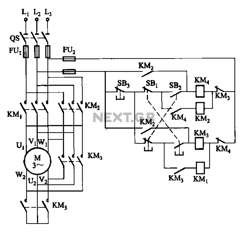
33 kW and above windlass with Y-conversion power-saving circuit The circuit design for a windlass rated at 33 kW and above incorporates a Y-conversion power-saving mechanism. This design is crucial for optimizing the efficiency of the windlass, which is commonly...
Another JYB type liquid level controller internal circuit is shown. This circuit employs a Schmitt trigger configuration, enhancing the reliability of the action level controller. The JYB type liquid level controller utilizes a Schmitt trigger circuit composed of transistors VT2...

The circuit provides a passband gain of 1 with a corner frequency of 10 kHz, designed to eliminate high-frequency noise such as hiss, ticking, and popping sounds. This circuit operates as a low-pass filter, effectively attenuating frequencies above the specified...
Warning: include(partials/cookie-banner.php): Failed to open stream: Permission denied in /var/www/html/nextgr/view-circuit.php on line 713
Warning: include(): Failed opening 'partials/cookie-banner.php' for inclusion (include_path='.:/usr/share/php') in /var/www/html/nextgr/view-circuit.php on line 713