
PC Watcher | Turn On and youll hear the Alarm

The PC Watcher circuit operates by monitoring the status of the computer and detecting any unauthorized attempts to access it. The circuit typically includes a microcontroller, which serves as the central processing unit, and various sensors or inputs that can detect physical access or intrusion attempts.
The components may include a motion sensor, a door contact switch, or a keypad that requires a code for access. When unauthorized access is detected, the microcontroller can trigger an alarm or send a notification, providing an immediate response to potential security breaches.
Power supply requirements for the circuit are usually modest, allowing it to be powered through the computer's USB port or a dedicated power adapter. The circuit can be compactly designed to fit within the confines of a small enclosure, making it suitable for integration into existing computer setups without occupying much space.
For installation, the circuit can be connected to the computer's case or positioned near entry points to the workspace. The veroboard layout should be organized to minimize interference and ensure reliable connections between components. Proper soldering and secure mounting of components on the veroboard are crucial to maintain the integrity and functionality of the circuit.
Overall, the PC Watcher circuit is an effective solution for individuals seeking to enhance their computer security by providing a simple yet effective means of monitoring unauthorized access attempts.This little PC Watcher circuit will help you to prevent unauthorised access to your personal computer. After construction on a small piece of veroborad, en.. 🔗 External reference
Related Circuits
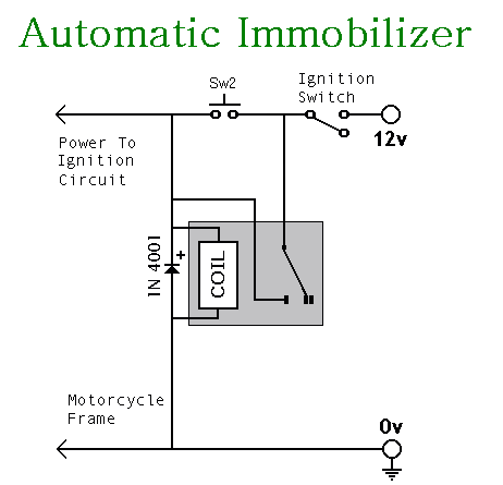
This circuit includes an intermittent siren output with automatic reset functionality. It can be activated manually via a key switch or a concealed switch, or it can be configured to activate automatically when the ignition is turned off. By...

The motorcycle anti-theft alarm circuit consists of a detection alarm circuit, a charging circuit, and an anti-theft control circuit, as illustrated in figure 7-94. The detection alarm circuit includes a mercury switch (S1), resistors (R1-R3), a capacitor (C), transistors...

The operating voltage for capacitors C1 and C2 should be raised to 25V if a 12V energy source is used. A general guideline is that the operating voltage of capacitors should be at least double the supplied voltage; for...
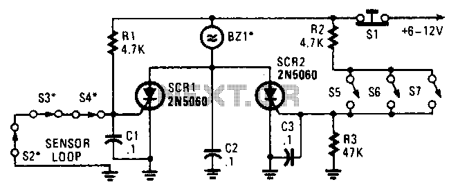
Two SCRs are utilized with two sensor loops. One loop employs series switches, while the other loop employs parallel switches. When a switch is actuated, the SCR is triggered. The alarm is designed to be a non-interrupting type. The circuit...

When the AC mains supply fails, this circuit triggers an alarm to alert the user. Additionally, it offers a backup light to assist in locating a flashlight or other emergency lighting. This circuit is designed to provide immediate notification and...

Various fire alarm circuits are discussed, featuring a new design that utilizes a thermistor and a timer. This circuit is straightforward and can be easily implemented. The thermistor exhibits low resistance at high temperatures and high resistance at low...