
Hammond organ circuit
In audio processing circuits, the frequency cut-off point between bass and treble channels is a critical aspect that influences sound quality and clarity. Typically, this cut-off frequency is determined by the design of filters used within the circuit, which can be either passive or active.
For a circuit analyzing bass and treble separation, a crossover filter design is commonly employed. The crossover filter divides the audio signal into different frequency bands, allowing for dedicated amplification and processing of bass and treble frequencies. The choice of cut-off frequency can significantly affect the overall audio experience.
1. **500Hz Cut-off**: This frequency is often used in audio applications where a more pronounced bass response is desired. It allows frequencies below 500Hz to be routed to the bass channel while higher frequencies are sent to the treble channel. This setting is suitable for music genres that emphasize low-end frequencies, such as hip-hop or electronic music.
2. **1KHz Cut-off**: A cut-off at 1KHz provides a balanced separation between bass and treble. It is a common choice for general audio applications, ensuring that both low and high frequencies are adequately represented. This frequency is ideal for a wide range of music and spoken word applications, providing clarity without overly emphasizing either end of the spectrum.
3. **5KHz Cut-off**: Setting the cut-off frequency at 5KHz primarily allows low frequencies below this threshold to be directed to the bass channel. This configuration is typically used in scenarios where high-frequency sounds are less critical, or where the focus is on bass-heavy content. It may also be beneficial in preventing high-frequency noise from interfering with the bass response.
The analysis of the circuit should include examining the filter design parameters, such as the order of the filters, component values, and the overall topology (e.g., Butterworth, Linkwitz-Riley). Additionally, simulations or measurements can be performed to verify the actual cut-off frequency in practice, as component tolerances and circuit layout can affect performance.
In conclusion, determining the appropriate frequency cut-off for bass and treble channels requires careful consideration of the desired audio characteristics and the specific application of the circuit. Each cut-off frequency offers distinct advantages and should be selected based on the intended use case and listener preferences.I could use some help analysing a circuit. Specifically the frequency cut-off between the bass and treble channels. Is it 500Hz, 1KHz or 5Khz. I`m.. 🔗 External reference
Related Circuits
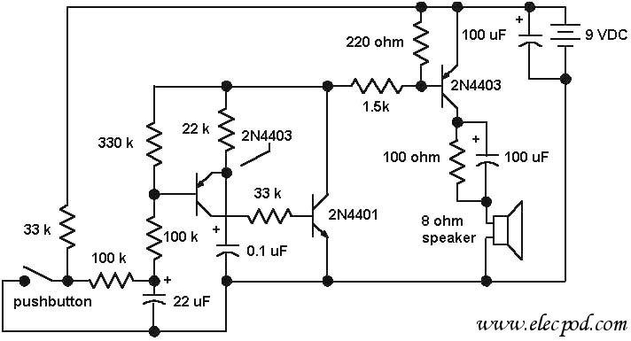
The core component of the circuit is a dual transistor flasher with frequency modulation applied to the base of the first transistor. When the pushbutton is pressed, the oscillation frequency increases to a peak, and when the button is...
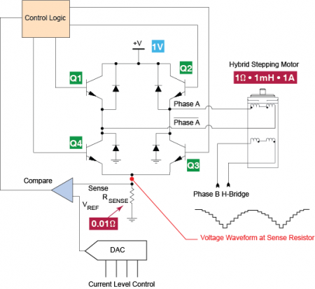
In today's blog, we are going to examine a bipolar chopper drive, a common method for precision current control in stepper motors. A bipolar chopper drive is an essential circuit configuration used in stepper motor control systems, particularly for achieving...
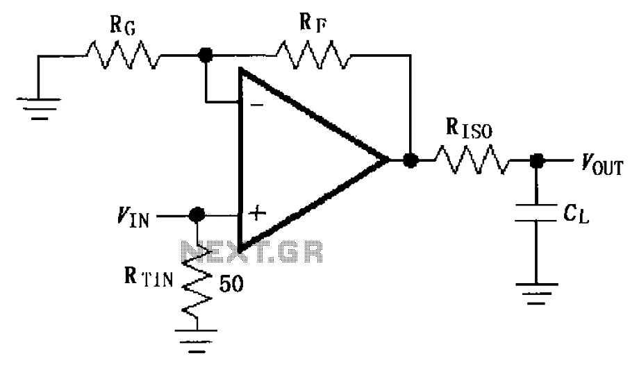
The circuit depicted in FIG demonstrates the MAX4450/4451 utilizing a capacitive load drive circuit with an isolation resistor (RISO). This configuration is situated between the output terminals and the load, along with an additional resistor, to mitigate overshoot and...
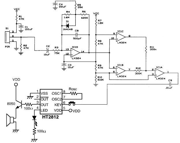
The operational amplifier IC1D modifies the frequency response to enhance the frequencies generated during motion detection while eliminating others, such as noise or gradual temperature variations. When the output voltage of IC1D exceeds 1.67V, it activates pins 8 and...
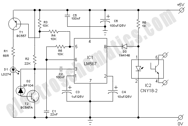
This simple and economical infrared model train detector circuit is designed specifically for hobbyists who want to incorporate a smart sensor to detect trains on their model railway track. The schematic diagram illustrates a straightforward configuration comprising an infrared...
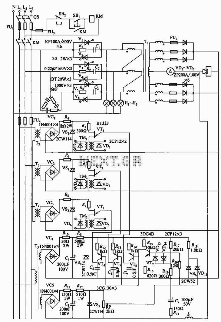
The 300A-18V three-phase thyristor power regulator circuit is designed for electrolysis applications. It can output a direct current of 3000A at an adjustable voltage of 18V, providing a power supply solution for various processing needs. The circuit comprises a...