
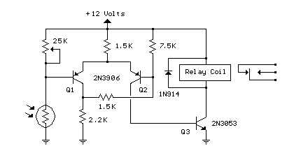
Photo Light with Relay
The described circuit utilizes a CMOS dual D flip-flop (CD4013) to create a toggle mechanism for controlling a relay or similar load via a momentary push button. The CD4013 consists of two independent D-type flip-flops, which can be configured to change their output state on the rising or falling edge of the clock signal generated by the push button.
When the push button is pressed, it sends a clock pulse to the flip-flop, causing it to toggle its output state. This output can then be used to activate a relay. The relay should be a double pole, double throw (DPDT) type to allow for versatile control of the load. The DPDT relay can switch both the load and provide feedback to the circuit, ensuring that the flip-flop maintains its state until the next button press.
To implement this, a single NPN transistor can be used to drive the relay coil. The transistor is controlled by the output of the flip-flop, allowing the relay to be energized or de-energized based on the state of the flip-flop. The relay contacts can be wired such that one set is used to control the load, while the other set can be used for feedback to the flip-flop, ensuring that the circuit behaves as intended.
For multiple control points, several push buttons can be connected in parallel to the clock input of the flip-flop. This configuration allows the relay to be toggled from different locations without the need for complex wiring or additional components. The circuit design provides a simple yet effective solution for remote control applications where momentary push button activation is required.
Additional considerations include debouncing the push button to prevent multiple toggles from a single press, which can be achieved using a capacitor and resistor in conjunction with the push button. Proper power supply decoupling and protection for the relay and transistor are also essential to ensure reliable operation.The circuit below uses a CMOS dual D flip flop (CD4013) to toggle a relay or other load with a momentary push button. Several push buttons can be wired in parallel to control the relay from multiple locations. The circuit below requires a double pole, double throw relay in conjunction with a single transistor to allow toggling the relay with a momentary push button. One set of relay contacts is used to control the load, while the other is used to provide feedb 🔗 External reference
Related Circuits
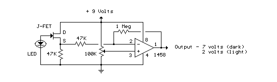
This circuit utilizes a JFET to receive signals from an LED and buffer them. The output voltage is managed using an IC 1458 or LM1458, which provides approximately 7 volts in darkness and experiences a drop of about 2...
The report provides information related to light sensors, photoresistors, comparators, and associated circuits. It contains extensive details regarding detection. Light sensors are devices that detect and respond to light levels in the environment. A common type of light sensor is...
LEDs lining the headliner will fade in when the door is opened and fade out when the door is closed. The necessary components include a circuit to utilize 12V power from the vehicle to illuminate 15 LEDs and control...
Competition among relay contacts in contactor control systems often leads to significant issues that can be cumbersome to address. In some cases, this requires the addition of numerous components. However, utilizing a negative temperature coefficient thermistor (NTC) for delay...
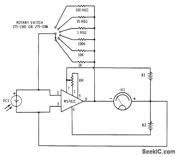
The circuit involves the switching of feedback resistors for an operational amplifier (op-amp) that is driven by a Radio Shack 276-115 selenium solar cell, resulting in a multirange linear light meter. A 1000-megohm resistor is utilized for the highest...

This design outlines a sensor circuit that utilizes an LED as a light sensor. The operational control and amplification of the output are managed by a 1458 integrated circuit (IC), which functions as an operational amplifier (op-amp). The circuit...
Warning: include(partials/cookie-banner.php): Failed to open stream: Permission denied in /var/www/html/nextgr/view-circuit.php on line 713
Warning: include(): Failed opening 'partials/cookie-banner.php' for inclusion (include_path='.:/usr/share/php') in /var/www/html/nextgr/view-circuit.php on line 713