
Photo Strobe Circuit
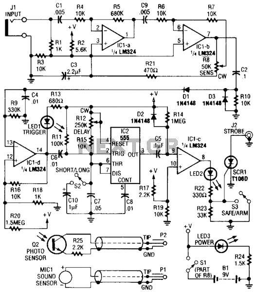
The circuit consists of several key components that work together to detect sound or light and trigger a strobe light for photographic purposes. The sound or light sensors connected to connector J2 generate an initial voltage signal in response to environmental stimuli. This voltage is then fed into two operational amplifiers, IC1-a and IC1-b, which serve to amplify the signal to a usable level.
The amplified signal is processed further to generate a positive trigger voltage. This is achieved through the diode D1 and resistor R3, which work in conjunction with operational amplifier IC1-d. The role of IC1-d is to further amplify the trigger voltage, ensuring that it is strong enough to drive subsequent components in the circuit.
The output from IC1-d is connected to two additional integrated circuits, IC2 and IC1, which are configured to control the triggering mechanism of the silicon-controlled rectifier (SCR1). SCR1 acts as a switch that controls the power to the strobe light. When the trigger voltage reaches a certain threshold, SCR1 is activated, allowing current to flow to the strobe, thereby producing a flash of light.
This circuit is particularly advantageous for capturing images of dynamic events that are difficult to photograph using conventional methods. The ability to synchronize the strobe with sound or light events enables photographers to capture precise moments, such as impacts or other rapid occurrences, making it a valuable tool in various photographic applications. Sound or light sensors corniected to J2 produce a voltage that is amplified by ICl-a and ICl-b. A positive trigger voltage that is developed by D1 and 1)3 and amplified by ICl-d, drives 1C2 and 1C1 to trigger SCR1. SCR1 is connected to a strobe. This device is handy for photographic purposes to take pictures of events that involve sound, such as impacts, ctc. 🔗 External reference
Related Circuits

Alarm system designs often require circuitry that can detect whether a phone line is active or broken. The primary challenge in this design is to draw less than 5 µA from the phone line, which operates within a voltage...
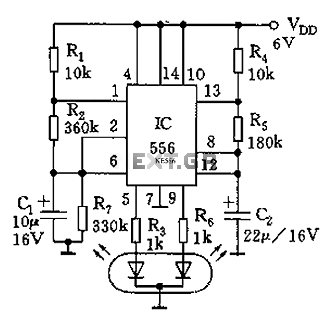
The circuit features a dual-core 556 timer IC and a light-emitting diode (LED) tube. The left half of the IC (556 1/2) comprises resistors R1, R2, capacitor C1, etc., generating a frequency of approximately 2 Hz in a multivibrator...
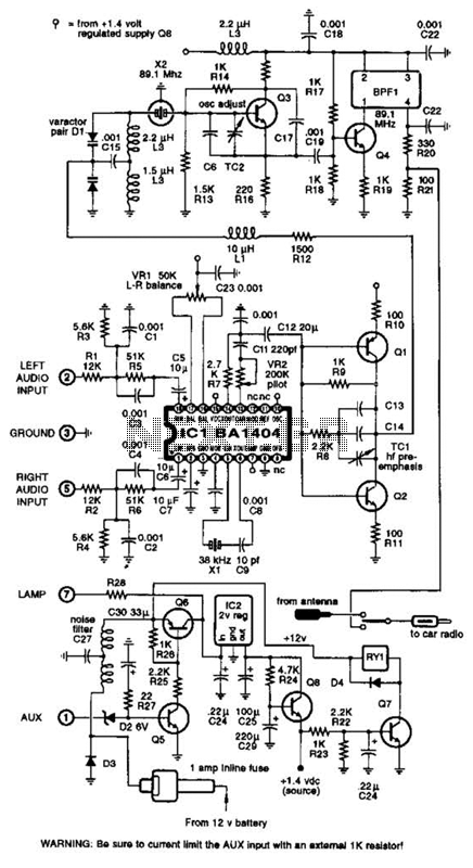
A BA1404 integrated circuit (IC) is utilized to generate a complete FM multiplex (MPX) signal. The chip incorporates all necessary circuitry. Components CI, R3, R4, and C4 are responsible for providing pre-emphasis. The transmitter operates on a single AA...
This circuit consists of two main components: a battery charger that provides a fixed output voltage of 5V DC, and a regulated power supply that allows for an adjustable output voltage ranging from 2 to 9 volts. The circuit design...
Fast rise-time high-voltage pulses have various applications, including EMC testing and device characterization. The circuit outlined here is a simple, cost-effective solution designed for the latter purpose. It can generate pulses ranging from 0 to 1000 V with currents...
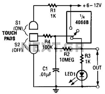
This touch-on switch can be activated through electrical means and can only be reset using a mechanical switch. When the touch terminal is activated by a finger, the SCR turns on and illuminates LED1. The circuit utilizes a silicon-controlled rectifier...
Warning: include(partials/cookie-banner.php): Failed to open stream: Permission denied in /var/www/html/nextgr/view-circuit.php on line 713
Warning: include(): Failed opening 'partials/cookie-banner.php' for inclusion (include_path='.:/usr/share/php') in /var/www/html/nextgr/view-circuit.php on line 713