
Photo Switch Circuit
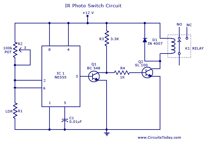
The described circuit utilizes the NE 555 timer IC configured in a comparator mode to create a photo switch that responds to varying light levels. The NE 555 is a versatile and widely used integrated circuit that can operate in different modes, including astable, monostable, and bistable configurations. In this application, it is set up to function as a light-sensitive switch.
The circuit comprises a light-dependent resistor (LDR) that acts as the light sensor. The resistance of the LDR decreases as light intensity increases, which alters the voltage at the non-inverting input of the NE 555. A reference voltage is established at the inverting input using a voltage divider formed by resistors. When the light intensity falls below a predetermined threshold, the voltage at the non-inverting input drops below the reference voltage, triggering the NE 555 to output a high signal.
This output signal is then used to drive a relay. The relay serves as a switch to control larger loads, such as lamps or industrial equipment, allowing them to be turned on or off based on the ambient light conditions. The circuit can be further enhanced by incorporating additional components such as capacitors for noise filtering and diodes for flyback protection across the relay coil.
The schematic diagram would typically show the connections between the LDR, NE 555, resistors, and relay, providing a clear visual guide for assembly. The simplicity of this circuit makes it an excellent choice for automatic lighting systems in both residential and commercial settings, ensuring energy efficiency and convenience.A simple photo switch circuit using NE 555 IC with diagram and schematic.This photo switch ons a relay when light intensity crosses limit.A light sensor circuit for home and industrial purpose 🔗 External reference
Related Circuits
This report outlines the operation and adjustment of a Phase Locked Loop (PLL) hum cancellation circuit designed to reduce residual hum from amplifiers. This circuit is particularly useful for Directly Heated Triode (DHT) amplifiers with AC-operated filaments, where a...
This circuit describes a simple 6-bit random number pseudo-generator used to study binary counters and, in particular, shift registers. Some basic background information about binary counters and shift registers is provided. In reality, there are dozens of different shift...
Unlike many units, this battery charger continuously charges at maximum current, tapering off only near full battery voltage. In this unit, the full load. This battery charger is designed to operate with a continuous charging mechanism, maintaining the maximum current...
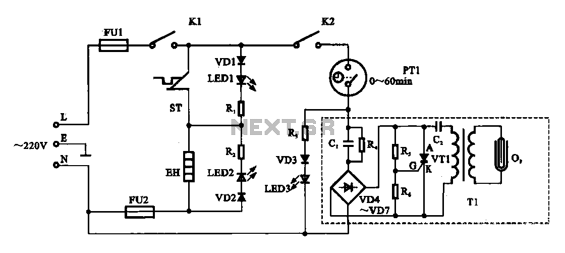
The dispenser (Aucma) temperature detection control circuit is designed to manage the temperature of the dispenser. It consists of two primary components: a heating control circuit and a fresh cabinet control circuit that provides power to an ozone generator....
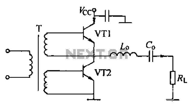
A complementary voltage switching Class D amplifier circuit is presented. Transistors VT1 and VT2 are 3DA12 types, while another transistor, VT3, is of the 3DK41C type. The collector is connected to a constant DC voltage of 12V. The input...
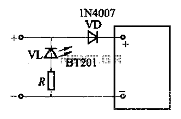
The adjustment potentiometer RP allows for modification of the over-voltage limit setting. In the event of reversed polarity in the DC power supply, there is a risk of damaging equipment components. To mitigate this risk, a reverse polarity protection...