
Photo Timer Circuit
The circuit utilizes a timing mechanism controlled by a potentiometer (R2) and a timing capacitor (C1). The potentiometer allows for adjustable resistance, which in turn modifies the charge time of the capacitor. The capacitor C1, rated at 100 µF, plays a crucial role in determining the timing interval; as it charges through R2, the voltage across C1 rises. This voltage is monitored at pin 3 of the integrated circuit (IC), which is configured as a timer or oscillator.
When the voltage across C1 reaches a specific threshold, the output at pin 3 transitions from a low state to a high state. This change in output state is what activates the relay. In its default condition, the output remains low, ensuring that the relay remains deactivated. The range of timing from 1 second to 100 seconds is achieved by adjusting the resistance of the potentiometer R2. A lower resistance results in a faster charge time for C1, thus shortening the timing interval, while a higher resistance increases the charge time, extending the timing interval.
This circuit is typically employed in applications requiring timed control, such as in delay timers, automatic lighting systems, or any scenario where a relay needs to be controlled based on a timed event. Proper selection of R2 and C1 is critical, as it directly influences the timing accuracy and stability of the circuit. Additionally, care must be taken to ensure that the relay's specifications match the output capabilities of the IC to prevent any potential damage or malfunction.Time is set by potentiometer R2 which provides a range or 1 sec. To 100 seconds with timing capacitor C1 of 100uF. The output at pin 3 is normally low and the relay is held off.. 🔗 External reference
Related Circuits
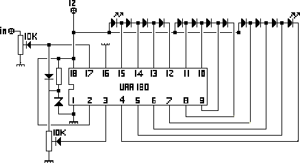
The NL3ASD schematic pages provide the schematics for a LED VU meter utilizing the UAA180 integrated circuit. The NL3ASD schematic pages feature a comprehensive design for a LED VU meter that employs the UAA180 IC, known for its audio signal...
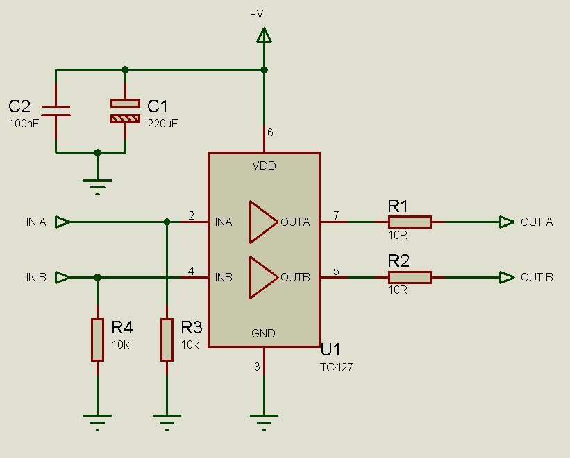
MOSFETs cannot simply be connected to the drive signal and expected to function correctly. Due to their construction, driving MOSFETs can be complex, particularly for beginners. Many users frequently seek assistance with MOSFET drive issues on various blogs, websites,...
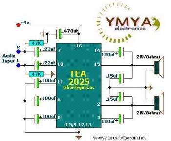
This is a simple portable audio amplifier circuit. The circuit is built around the TEA2025 integrated circuit, which is a monolithic audio amplifier housed in a 16-pin dual in-line package manufactured by UTC. The circuit features an internal thermal...
This project involves an automatic street light or lamp circuit designed to activate outdoor lights, such as garden lamps and night lights, automatically at sunset and turn them off at sunrise. The circuit is sensitive and versatile, capable of...
The schematic diagram of the MS Decoder may appear complex, but it is relatively straightforward. Initially, both the Mid and Side signals are buffered using unity gain inverting buffers, which are constructed around IC1b and IC2b. This buffering serves...
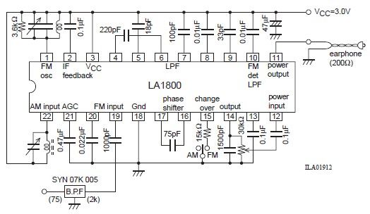
This portable AM/FM radio circuit is designed using the LA1800 integrated circuit (IC) along with several external components. The LA1800, manufactured by Sanyo Semiconductors, requires only a few additional components for its operation. The output signal is directed to...