
street light lamp circuit
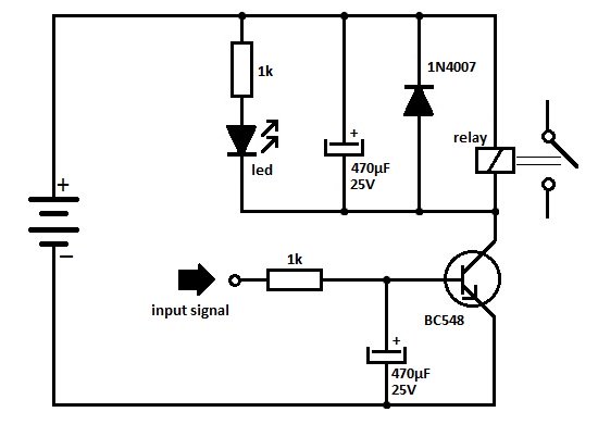
The automatic street light circuit primarily consists of a light-dependent resistor (LDR), two 2N3904 NPN transistors, a relay, and a variable resistor (VR) for sensitivity adjustment. The LDR plays a critical role in detecting ambient light levels. In bright conditions, the LDR's low resistance allows current to flow, keeping transistor Q1 in the off state, which in turn keeps Q2 off, preventing the relay from activating. As ambient light decreases at dusk, the LDR's resistance increases, which raises the voltage at the base of Q1, turning it on. This action also turns off Q2, allowing the relay to engage and power the connected load.
The circuit can be powered by a DC source of 6V, 9V, or 12V, with the relay being rated for the same voltage to ensure compatibility and proper operation. The variable resistor (50K VR) allows for fine-tuning of the light sensitivity, enabling the user to set the threshold at which the circuit activates based on the local lighting conditions.
The relay used in the circuit acts as a switch to control the higher voltage AC load. It is essential to select a relay that can handle the maximum load current and voltage to prevent damage or failure of the circuit. The simplicity of the design allows for easy assembly and troubleshooting, making it an excellent choice for DIY enthusiasts looking to automate outdoor lighting solutions.Here is a very useful project of an automatic street light or lamp circuit which can be used to activate your outdoor lights like garden lamps, night lights etc. automatically when the sun set and turn off automatically when the sun rises. The circuit is quite sensitive and versatile and can be used to activate any 220 volt AC device at night and
turn off in day all you have to do is simply connect the device with the load point. You can also connect a 220V plug socket with the load point to connect different electronic devices but make sure the relay points can able to handle the provided load. The circuit is simple using two 2N3904 transistors and few other components. The 50K VR (Variable Resistor) is used to adjust the circuit to activate the relay on the required darkness.
The circuit can be operated with 6 volts, 9 volts and 12 volts but it is important to use the same voltage relay also. The circuit is actually a dark detecting circuit or we can also say it dark / light sensor circuit. The two transistor used in the circuit are working as switches. When light falls on the LDR its resistance decreases and the voltage at the base of Q1 will increase which will switch on the Q1 and the Q2 will remain switch off.
When there is no light on the surface of the LDR its resistor increases, which will switch off the transistor Q1 and the voltage at the base of Q2 increases and hence the transistor Q2 will switch on and activates the relay switch. 🔗 External reference
Related Circuits
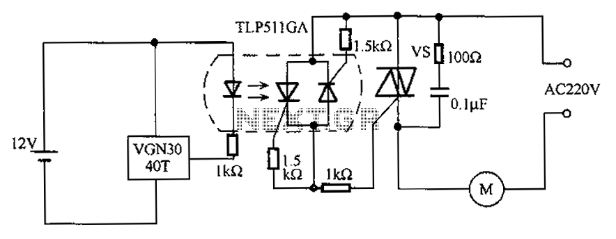
The circuit utilizes an integrated Hall effect sensor for an AC motor control system. It operates by detecting the presence of magnets or other magnetic objects near the Hall IC element of the induction motor. This configuration functions as...
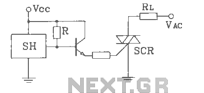
SH Hall opened with a double silicon output interface circuit The SH Hall sensor circuit is designed to provide a dual silicon output interface, which enables enhanced signal processing capabilities. This circuit typically integrates a Hall effect sensor that detects...

The circuit operates at a distance of 3 feet from the oscillating pulse output of a 555 timer generating a 40kHz signal, driving a T-40-16 transducer to emit ultrasonic signals at the same frequency. The circuit is powered by...
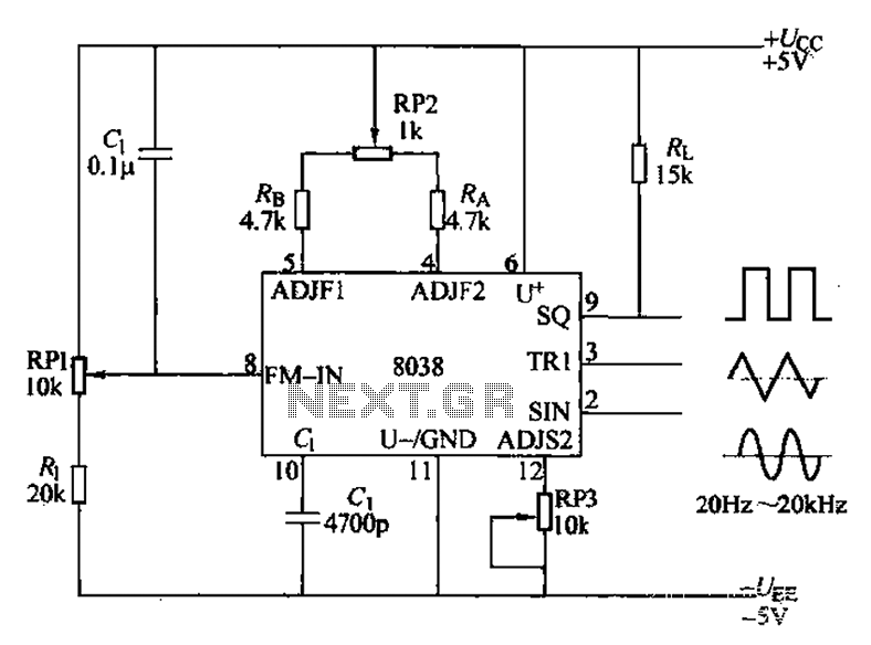
The audio function generator integrated circuit ICL8038 is capable of producing square waves, triangle waves, and sine waves. The electrical resistance and potentiometer RP1 are utilized to determine the 8-pin DC potential Ua, which is typically set to 2Ucr/3....
One of the serious problems in relay-operated circuits is the relay clicking or chattering during the on/off operation of the relay driver transistor. This issue can lead to unreliable circuit performance and may cause premature wear of the relay...
Wireless headphone transmitter and receiver systems are now widely available in the market, offering a variety of pricing options along with reliable technical specifications for various applications. These include wireless headphones for televisions, computers, and earbuds. A wireless headphone...