
under?-over voltage detector

Part List
R1=2Kohm/V minus 10Kohm R6-11=2.2Kohm D3-5=1N4001
R2-9-10=1Kohm R7-12=4.7Kohm D4=3V3 0.5W Zener
R3-8=10Kohm RV1-2=10Kohm pot. IC1-2=LM741
R4=1.2Kohm D1=6V8 0.5W Zener Q1-2=BC214
R5=47Kohm D2=5V6 0.5W Zener RL1-2=12V >120ohm Relay
The circuit described is a precision DC undervoltage relay switch utilizing an operational amplifier (op-amp) configured as a voltage comparator. In this configuration, the op-amp compares the voltage at its inverting input (pin 2) with the voltage at its non-inverting input (pin 3). When the voltage at pin 3 exceeds the reference voltage at pin 2, the output of the op-amp switches high, activating the relay (RL1-2). The relay is designed to operate at voltages exceeding 5 volts, with the exact trip point adjustable through the resistor R1.
For over-voltage detection, the circuit allows for trip points as low as 10 mV to 3 volts when the input voltage is applied directly to pin 2. For input voltages greater than 3 volts, a range resistor must be included to ensure that the voltage at pin 2 remains within the operational limits of the op-amp. The design also incorporates the flexibility to convert the circuit into an undervoltage switch by swapping the connections of pins 2 and 3.
To enable the circuit to work with AC voltage signals, an additional rectification stage is required to convert the AC input into a suitable DC voltage. This modification allows for broader applications of the circuit in various voltage monitoring tasks.
The part list provided includes various resistors (R1 to R7), potentiometers (RV1-2), zener diodes (D1 to D4), a rectifier diode (D3-5), transistors (Q1-2), and the relay (RL1-2), which are critical for ensuring the correct functionality and reliability of the circuit. The LM741 op-amp is the core component, providing the necessary voltage comparison capabilities. The specified values for the components allow for precise tuning of the voltage thresholds, making this circuit suitable for various applications in voltage monitoring and control systems. In Fig.1 A precision DC under?voltage relay switch. The opamp is wind as a voltage comparator, with a reference voltage applied to pin 2 and the test voltage applied to pin 3: the relay turns on when the pin 3 voltage exceeds that of pin 2. The circuit can be made to trip at any voltage in excess of 5 volts by suitable choice of R1 value. In Fig. 2 An over-voltage switch that can be used to trip at any pre-set voltage in excess of about 10 mV. The input voltage can be connected directly to pin 2 if trip values in the range 10mV to 3Volts are required.
For voltages in excess of 3 Volts, a suitable range resistor must be connected in the position shown, to keep the pin 2 Voltage drive to suitable level. The circuit can be converted to an under?voltage switch by transposing the pin 2 and pin 3 connections of the op-amp.
The circuit can be used as an AC voltage switch by first rectifying the AC input signal. Part List R1=2Kohm/V minus 10Kohm R6-11=2.2Kohm D3-5=1N4001 R2-9-10=1Kohm R7-12=4.7Kohm D4=3V3 0.5W Zener R3-8=10Kohm RV1-2=10Kohm pot. IC1-2=LM741 R4=1.2Kohm D1=6V8 0.5W Zener Q1-2=BC214 R5=47Kohm D2=5V6 0.5W Zener RL1-2=12V >120ohm Relay
🔗 External reference
Related Circuits
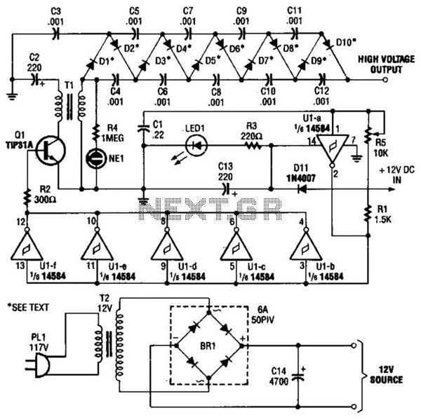
In the miniature high-voltage DC generator, the circuit receives input from a 12 V DC power supply, which is amplified to produce a 10,000 V DC output. This process induces a pulsating signal of opposite polarity in the secondary...
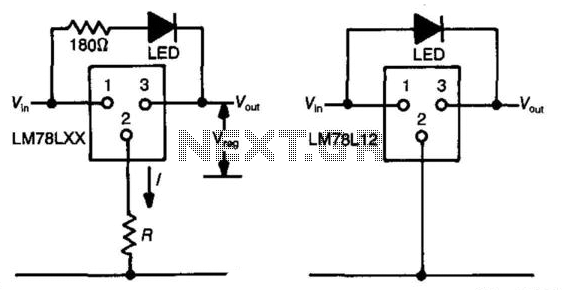
The three-terminal regulator device (LM78LXX) provides an output voltage (Vout) equal to the input voltage (Vm) until the input voltage exceeds the output voltage by 1.5 to 2 volts. A regulated voltage (Vreg) is achieved at this point, with...
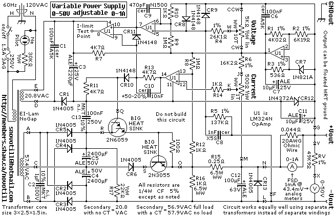
A reverse-engineered circuit diagram of a high-end commercial variable laboratory power supply. This unit is constructed using a standard operational amplifier and readily available components. While the design employs a single transformer with dual output windings, it can also...

Converter circuits are commonly utilized in various applications, and there are several types available. A simple frequency-to-voltage converter circuit uses the IC LM331, which is essentially a precision voltage-to-frequency converter. This IC has numerous applications, and in this instance,...
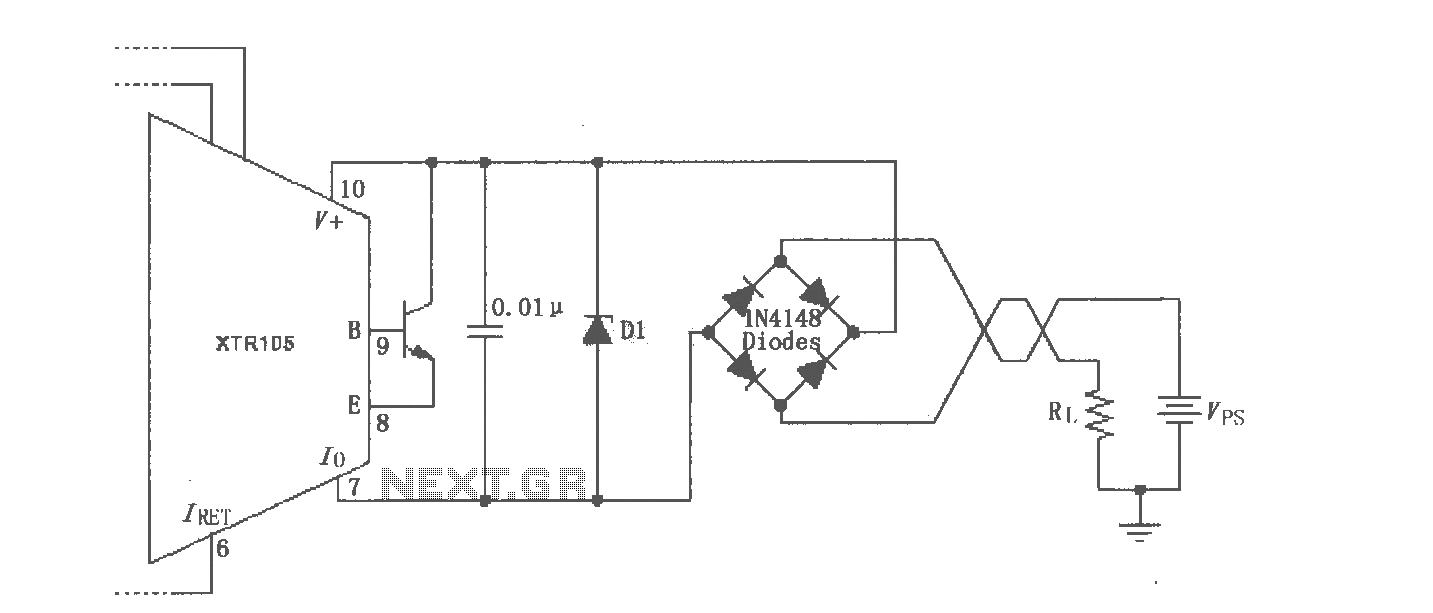
The XTR105 reverse voltage and over-voltage surge protection circuit is illustrated. A Zener diode rated at 36V can be utilized, with options including 1N4753A or 1N6286A. The maximum supply voltage (Vps) should be less than the minimum breakdown voltage...
This simple and inexpensive circuit can produce a dual (positive and negative) voltage from a single supply input. It is therefore extremely useful for powering opamp and other circuits that require a dual voltage from a single battery. The...