
Infrared (IR) Proximity Detector
The infrared (IR) proximity detector circuit operates by using a matched pair of an infrared emitter and detector. The emitter emits IR light, which reflects off nearby objects and is detected by the detector. The LM567 tone detector IC plays a crucial role in this circuit, particularly through its voltage-controlled oscillator (VCO) functionality. The VCO is designed to produce pulses at a frequency of approximately 909 Hz, which is determined by the values of capacitor C1 and resistor R1.
When the IR light reflects off an object and is received by the detector, it generates a signal that is fed into the tone detector IC. The IC compares the input frequency from the detector with its own generated frequency. If the input frequency deviates significantly from the expected frequency, the pull-up resistor R3 ensures that the output remains at a stable 5 volts. This condition indicates that no object is within proximity. Conversely, when an object is detected and the frequencies are close enough, the output at pin 8 transitions to a low state, indicating proximity.
For applications requiring higher current output, an amplifying transistor can be connected to the output stage of the circuit. This allows the circuit to drive larger loads or activate additional components based on the proximity detection. The overall design of the circuit is effective for various applications, including object detection in robotics, automation systems, and safety devices. Proper selection of the emitter and detector pairing, along with the tuning of the VCO frequency, is essential for optimizing the performance of this IR proximity detector circuit.This is infrared (IR) proximity detector circuit. A matched infrared emitter and detector pair is used in this circuit. The voltage controlled oscillator section of the LM567 tone detector IC is used to set the emitter LED pulses at frequency. In this circuit, the center frequency of the VCO is set to about 909 Hz by combination of capacitor C1 an
d Resistor R1. Here is the circuit: A signal is generated for the tone detector IC as the response to the detected reflected light from the emitter. The input frequency is compared with the generated frequency by the decoder. If the frequency is far, R3, 10K pull up resistor, holds it to 5 Volts. If the frequency is close enough, the pin 8 is sent to LOW (ground). An amplifying transistor can be added for higher currents as needed. [Circuit`s schematic diagram source: mondotronics. com] We aim to transmit more information by carrying articles. Please send us an E-mail to wanghuali@hqew. net within 15 days if we are involved in the problems of article content, copyright or other problems.
We will delete it soon. 🔗 External reference
Related Circuits
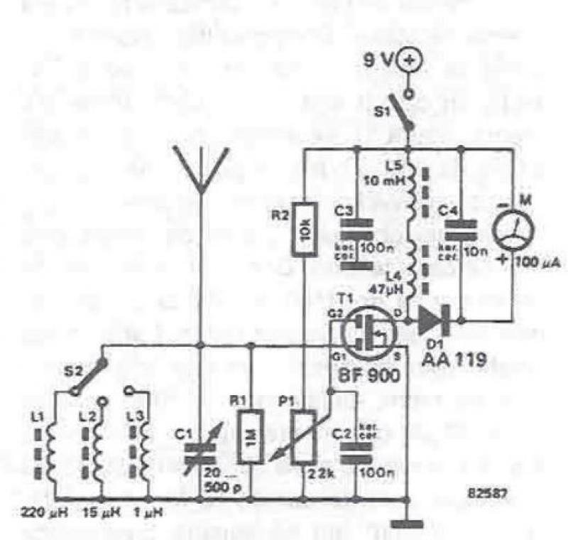
An RF field detector circuit suitable for measuring and verifying the power of antennas and transmitters can be constructed using transistors and common electronic components. This circuit employs a radio frequency transistor, specifically a MOS-FET with two gates. The...
One of the simplest methods of metal detection is through a beat frequency oscillator. The circuit consists of two balanced oscillators: one provides a reference signal, while the other acts as the detector element. The frequency of the reference...
In Fig.1 see a DC current sensing switch, in which the current is applied from an 8 to 16 Volt supply. The R1 value is chosen so that it generates roughly 100 mV at the required trip current. In...
A ringer interface circuit is designed to buffer the output of a central telephone system, which connects to multiple ringers distributed throughout a building. This circuit addresses an issue where the line overloads when ringing, requiring a reset. The...

This circuit is designed for line detection in a robot project. A proper match between the transmitter and the detector is crucial for optimal operation, particularly when the hole is large. The robot is equipped with a simple system...
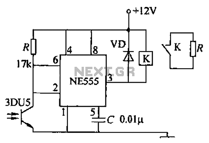
A transmitting circuit powered by an infrared light-emitting diode emits light. The receiving circuit, shown in the figure, utilizes a transistor (3DU5) to receive the infrared light and output the received signal. The signal is sent to terminal 3...