
Photosensitive resistor circuit diagram of an automatic lighting
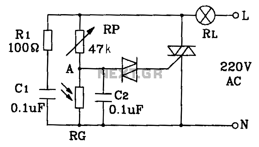
The automatic lighting circuit employs a photosensitive resistor (LDR) as the primary sensor, which detects ambient light levels. When the light intensity falls below a predetermined threshold, typically at dusk, the LDR's resistance increases, triggering the circuit to activate the lighting system. Conversely, during daylight hours, the increased light intensity causes the LDR's resistance to decrease, which in turn deactivates the lights.
The circuit can be designed using a simple transistor switch or a relay, depending on the required load capacity. For smaller loads, a transistor such as a NPN type can be used, where the LDR is connected in a voltage divider configuration with a fixed resistor. The output from the divider is fed into the base of the transistor. When the resistance of the LDR increases at low light levels, sufficient base current flows, allowing the transistor to conduct and turn on the connected load, such as LED lights or fluorescent lamps.
For larger loads, a relay can be employed. The LDR and fixed resistor create a similar voltage divider, which activates a relay coil when the ambient light is low. The relay then closes its contacts, allowing mains power to flow to the lighting fixtures. This configuration provides isolation from high voltage and can handle larger currents safely.
To enhance functionality, additional components such as a timer or a microcontroller can be integrated into the circuit. This allows for more complex behaviors, such as dimming the lights or setting specific on/off schedules based on time rather than just light levels.
Overall, this automatic lighting system is efficient and practical for environments requiring reliable illumination during nighttime or low-light conditions, contributing to safety and convenience in various public and private settings. By the photosensitive resistor of this circuit is a circuit diagram of the automatic lighting for hospitals, dormitories corridor and public places. It automatically lights off during the day and at night.
Related Circuits

A simple audio amplifier with a 10 Vpp output designed for use with the AD633 ring modulation chip. The datasheet for the chip is available, and the circuit will utilize the XR2206 function generator IC for the modulation input....
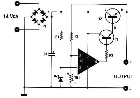
This automatic battery charger circuit is ideal for charging batteries used in alarm systems that require battery buffering. Caution must be exercised when connecting the battery to ensure correct AC polarity. It is essential to meticulously follow the schematic...
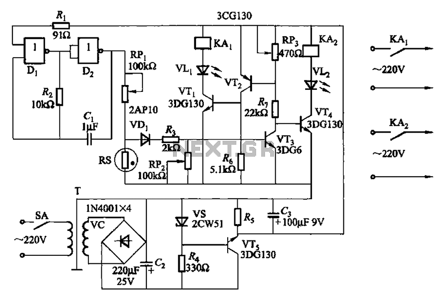
Two NAND gates (Di, Dz) and a resistor (Rz) along with capacitors (C1, etc.) form an RC self-excited multivibrator with an oscillation frequency of 2.5 Hz and an oscillation amplitude of 4 V. This circuit is used as a...
The controllable multivibrator, as illustrated in figure 14-40, consists of a 555 timer along with resistors RA, RP1, and capacitor C1. The oscillation frequency is influenced by the control voltage applied to pin 5. This control voltage is determined...

This is a circuit design for a doorbell that produces a sound resembling that of a bird. The circuit is controlled by an NPN transistor. The operation begins when P1 is set to an experimental value, starting with approximately...

This circuit facilitates on/off switching, soft starting, current monitoring, current tripping, and overcurrent protection for a 30 Vdc power supply, accommodating normal load currents of up to 2 A. The switch is activated by an "on" command pulse and...