
Phototransistor 555 Timer
The described circuit utilizes the 555 timer IC configured in a monostable or astable mode, depending on the specific application requirements for detecting light levels. The primary function of the circuit is to detect changes in light intensity, which is critical for applications like train detection systems. The 555 timer operates by generating a pulse when the light level crosses a predefined threshold, activating the output to drive a load, such as light-emitting diodes (LEDs) or relays.
In the schematic, the 555 timer's DISCHARGE terminal (Pin 7) is employed to provide a secondary output. This configuration allows for the sinking of larger currents, making it suitable for driving devices like relays, which may require more current than what an LED can handle. This versatility in output makes the circuit adaptable for various applications beyond just visual indicators.
An optional resistor, R6, can be integrated into the design to modify the sensitivity of the circuit. By adjusting the resistance value, the detection voltage range can be compressed, allowing for finer control over the light detection threshold. However, it is noted that this adjustment does not completely resolve the issue of a wide detection band, which may still result in undesired triggering or sensitivity to ambient light changes.
The circuit's performance can be visually represented through graphs that illustrate the relationship between input voltage levels and the corresponding output behavior. Understanding these characteristics is essential for proper tuning and optimization of the circuit for specific environmental conditions and operational requirements. Overall, the 555 timer circuit serves as a robust solution for light detection applications, particularly in scenarios where reliable performance is crucial.This page shows three circuits for using the 555 timer IC as a photocell controlled train detector. The circuit is shown driving light emitting diodes but any load of less than 200 milliamps could be used. Shown on the schematic is a secondary output that uses the open collector at the DISCHARGE terminal (Pin 7) of the timer.
This output can sink a fairly large current and would be ideal for driving relays. An optional resistor, R6, can be added to the circuit to lower and compress the detection voltage range but this only partially alleviates the problem of the wide detection band. The graphs at the bottom of the diagram show the input voltages at whic 🔗 External reference
Related Circuits
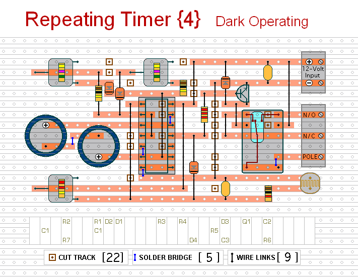
This circuit functions as the inverse of Repeating Timer No. 3. Its operation is constrained to the hours of darkness. The variable resistor (preset) allows for the selection of the darkness level at which the timer will activate. The circuit...
A variable frequency, variably duty cycle 555 configuration is set up in astable mode. A set of potentiometers is utilized to achieve a wide range of control. The output is functioning well; however, there is an issue. The circuit...
This is a lamp timer capable of operating two separate relay switches. Outputs can be in three (or restricted to two) states: OFF, delayed ON and constant ON. Delayed ON mode is indicated by the LEDs. The source code...
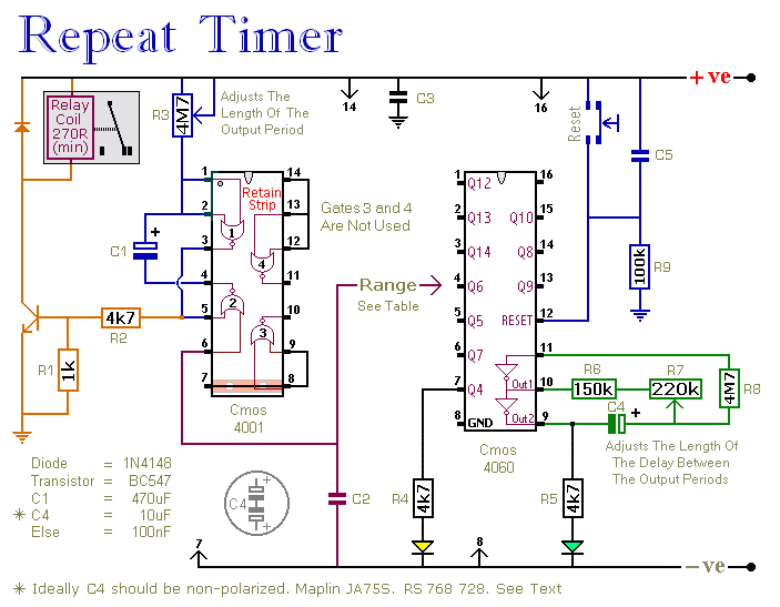
This circuit features an adjustable output timer capable of re-triggering at regular intervals. The output duration can range from a fraction of a second to over half an hour, and it can be configured to recur at regular intervals...
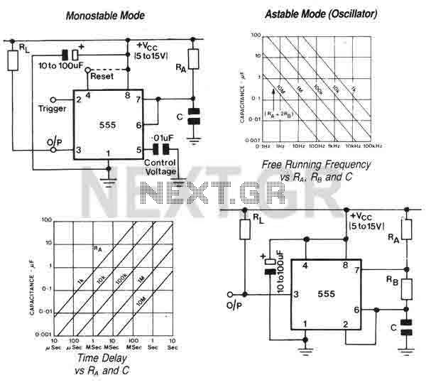
The 555 is a highly stable device for generating accurate time delays or oscillation. Additional terminals are provided for triggering or resetting if desired. In the time delay (monostable) mode of operation, the time is precisely controlled by one...
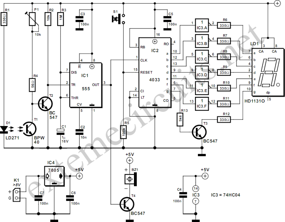
The circuit described here counts the number of times an infrared beam is interrupted. It can be utilized to count the number of individuals entering a room or to track how often an object, such as a ball, passes...
Warning: include(partials/cookie-banner.php): Failed to open stream: Permission denied in /var/www/html/nextgr/view-circuit.php on line 713
Warning: include(): Failed opening 'partials/cookie-banner.php' for inclusion (include_path='.:/usr/share/php') in /var/www/html/nextgr/view-circuit.php on line 713