
Astable/Monostable oscillator using 555 IC

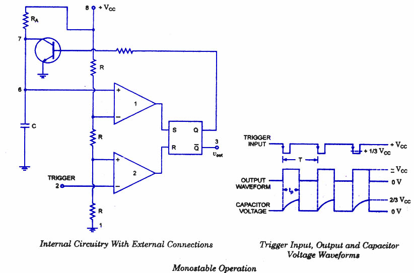
The 555 timer IC operates in three primary modes: monostable, astable, and bistable. In the monostable mode, the device generates a single output pulse of a specific duration triggered by a negative edge on the trigger pin. The duration of this pulse is determined by the external resistor (R) and capacitor (C) connected to the timing pins (pins 6 and 2). The time period can be calculated using the formula T = 1.1 * R * C, where T is the time in seconds.
In astable mode, the 555 functions as an oscillator, producing a continuous square wave output. The frequency and duty cycle of this waveform are determined by two resistors (R1 and R2) and a capacitor (C). The frequency (f) can be calculated with the formula f = 1.44 / ((R1 + 2*R2) * C), and the duty cycle can be adjusted by varying the values of R1 and R2.
The device features a robust output stage capable of sourcing or sinking up to 200mA, making it suitable for driving various loads, including LEDs and small relays. The output can also interface directly with TTL logic levels, allowing for seamless integration into digital circuits.
For optimal performance, supply decoupling capacitors should be placed as close to the IC as possible. This practice minimizes voltage fluctuations and noise, ensuring stable operation. A typical configuration might include a 0.1µF ceramic capacitor in parallel with a larger electrolytic capacitor (e.g., 10µF) to provide both high-frequency and low-frequency decoupling.
In summary, the 555 timer IC is a versatile and widely used component in electronic circuits, capable of generating precise timing intervals and oscillations with simple external components. Its adaptability and ease of use make it a fundamental building block in both hobbyist projects and professional applications.The 555 is a highly stable device for generating accurate time delays or oscillation. Aditional terminals are provided for triggering or resetting if desired. In the time delay (monostable) modeof operation the time is precisely controlled by one extrernal resistor and one capacitor. For stable operation as an oscillator, the free running frequency and the duty cycle are both accurately controlled with two external resistors and one capacitor.
The circuit may be triggered and reset on falling waveforms and the output structure can source or sink up to 200mA or dive TTL directly. This IC may also be correctly supplied marked as MC1455PI. Supply decoupling must be provided close to the IC to coun
Related Circuits
The frequency formula of a 555 oscillator is well-known. For given resistors and capacitors, the frequency can be calculated using a specific formula derived from mathematical principles. The 555 timer IC is widely used in various applications, including oscillators, timers,...
A power transistor with a voltage drop of 4 volts and a current of 3 amps may dissipate approximately 12 watts of heat, presenting a challenge in series regulators. In contrast, a saturated transistor or MOSFET with a voltage...
This circuit employs an HgCdTe demodulation device that can be cooled to 77K using liquid nitrogen. It utilizes a constant current bias for the demodulation device, which is connected to the input port. The voltage amplification factor is 200,...
Are you familiar with the basics and applications of the 555 timer IC? Are you looking for a book that provides all these basics? If so, CircuitsToday has started an online store where you can purchase books on the...
The major functional blocks necessary for designing a general-purpose audio oscillator are outlined, along with the details of the current prototype. The implementation is in the mode of an analog computer, as the desired outputs are sine and cosine...
On astable multivibrators, the duty cycle is typically fixed unless a potentiometer is incorporated. However, even with a diode in parallel with resistor R2, the duty cycle will only be less than 50%. To initiate a new thread, one...