
Phototransistor for High Impedance Voltmeter

The high impedance voltmeter circuit is particularly beneficial in applications where minimal circuit loading is essential, such as in phototransistor testing. The circuit typically consists of a high-value resistor in series with the multimeter, which allows for accurate voltage readings without significantly affecting the circuit under test. The design can include operational amplifiers configured as voltage followers to further isolate the measurement device from the circuit, ensuring that the voltmeter’s resistance does not influence the behavior of the phototransistor.
In practical implementations, the circuit may utilize a combination of resistors and capacitors to filter noise, stabilize readings, and improve response time. The choice of components should be made carefully, considering the frequency response required for the application. Additionally, the multimeter settings should be selected to match the expected voltage range, ensuring the highest possible accuracy.
When measuring the phototransistor, it is crucial to ensure that the light source is consistent, as variations in light intensity can lead to fluctuations in voltage readings. The circuit's design should accommodate variations in phototransistor characteristics, such as different types or models, which may exhibit different conductance properties under similar lighting conditions.
Overall, the high impedance voltmeter circuit provides a valuable tool for accurately measuring voltages in high resistance environments, particularly when working with sensitive components like phototransistors. This design allows for effective testing and validation of phototransistor functionality without compromising the integrity of the circuit being measured.This circuit is designed to provide an inexpensive way to create a High Impedance Voltmeter while making use of an inexpensive analog or digital multi meter. The circuit is specifically designed for testing phototransistors. This the figure for the circuit; When measuring voltages in high resistance circuits the resistance of the voltmeter itself
has an effect on the circuit. For example if the voltage across a 1 Mega ohm resistor is measured with a voltmeter that has an internal resistance of 1 Mega ohm then the total resistance in that part of the circuit is effectively halved (two 1 M resistors in parallel = 500K ohms). In another example; If a voltmeter with a 1 Mega ohm resistance is placed in series with a 1 Mega ohm resistance there will in effect be two - 1 Mega ohm resistances in series, the resistor in the circuit and the resistance of the voltmeter.
Under these conditions the maximum voltage that the voltmeter could show would be 1/2 of the supply voltage. This is the principle work of the circuit. Phototransistors, when used to detect a train position essentially have two states of conductance. When the phototransistor is dark it has LOW conductance and the voltage across it will be HIGH if the phototransistor is has either visible or infrared light falling on it then its conductance will be HIGH and the voltage across it will be LOW.
If the high impedance voltmeter circuit is used to measure the voltage across the phototransistor when it is dark it will not load down the circuit and should indicate almost 100 percent of the supply voltage. 🔗 External reference
Related Circuits
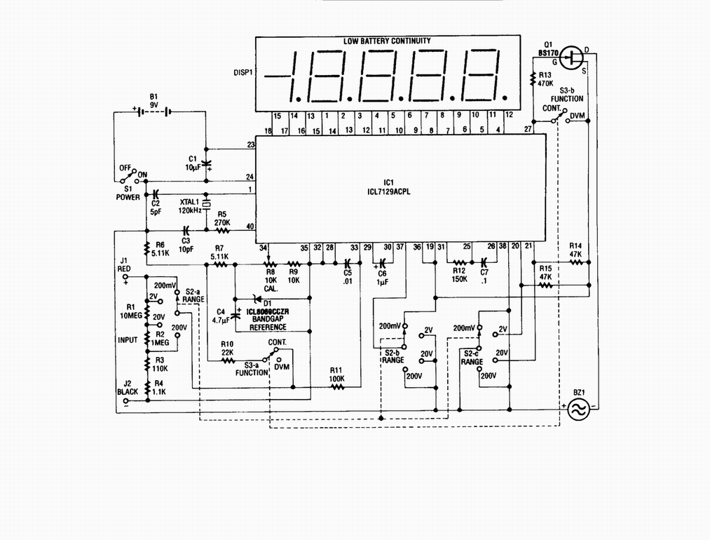
Single-chip digital voltmeter. This 4 1/2-digit DVM circuit is built around a Maxim ICL7129ACPL A/D converter and LCD driver. An ICL8069 CCZR 1.2-V band-gap reference diode is used for accuracy. The described circuit is a single-chip digital voltmeter (DVM) utilizing...
This is a light dimmer circuit. It does not include any special features and is a typical TRIAC-based dimmer circuit. This circuit is designed to operate with... A TRIAC-based light dimmer circuit is a common electronic design used to control...
These are circuits of high impedance low capacitance buffer and high impedance low capacitance amplifier. The first figure is a high impedance low capacitance. High impedance low capacitance circuits are critical in various electronic applications, particularly in signal processing and...
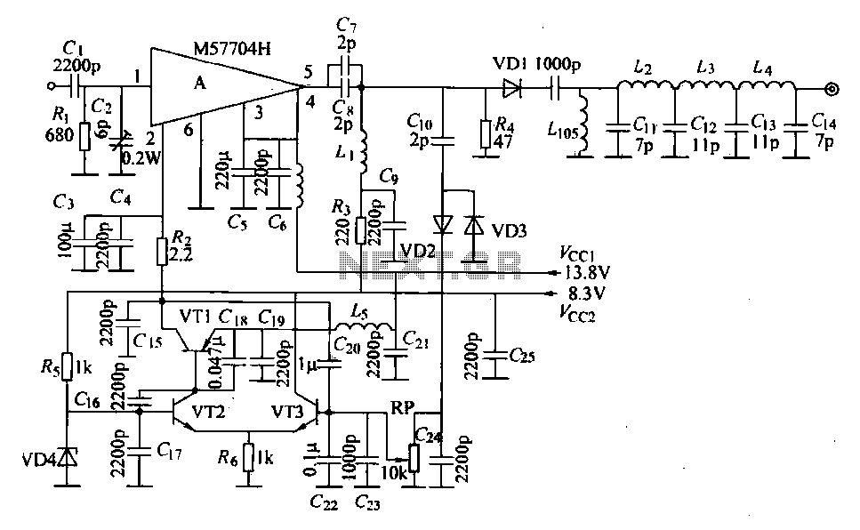
The FM radio transmitter is a high-frequency amplifier circuit that utilizes the Mitsubishi frequency set, specifically the M57704H discharge path. It operates within the frequency range of 457-458 MHz and has a transmission power of 5 watts. As illustrated...

An expanded scale voltmeter (ESV) can be crucial for aircraft operation. This assertion is based on the dependency of the radio link, which allows control of the aircraft, on nickel-cadmium (NiCd) batteries located in both the transmitter and receiver....
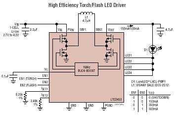
The LTC3453 is a synchronous buck-boost DC/DC converter optimized for driving up to 4 white LEDs at a combined current of up to 500mA from a single Li-Ion battery input. The regulator operates in either synchronous buck, synchronous boost,...
Warning: include(partials/cookie-banner.php): Failed to open stream: Permission denied in /var/www/html/nextgr/view-circuit.php on line 713
Warning: include(): Failed opening 'partials/cookie-banner.php' for inclusion (include_path='.:/usr/share/php') in /var/www/html/nextgr/view-circuit.php on line 713