
PIC Analogue Synthesizer
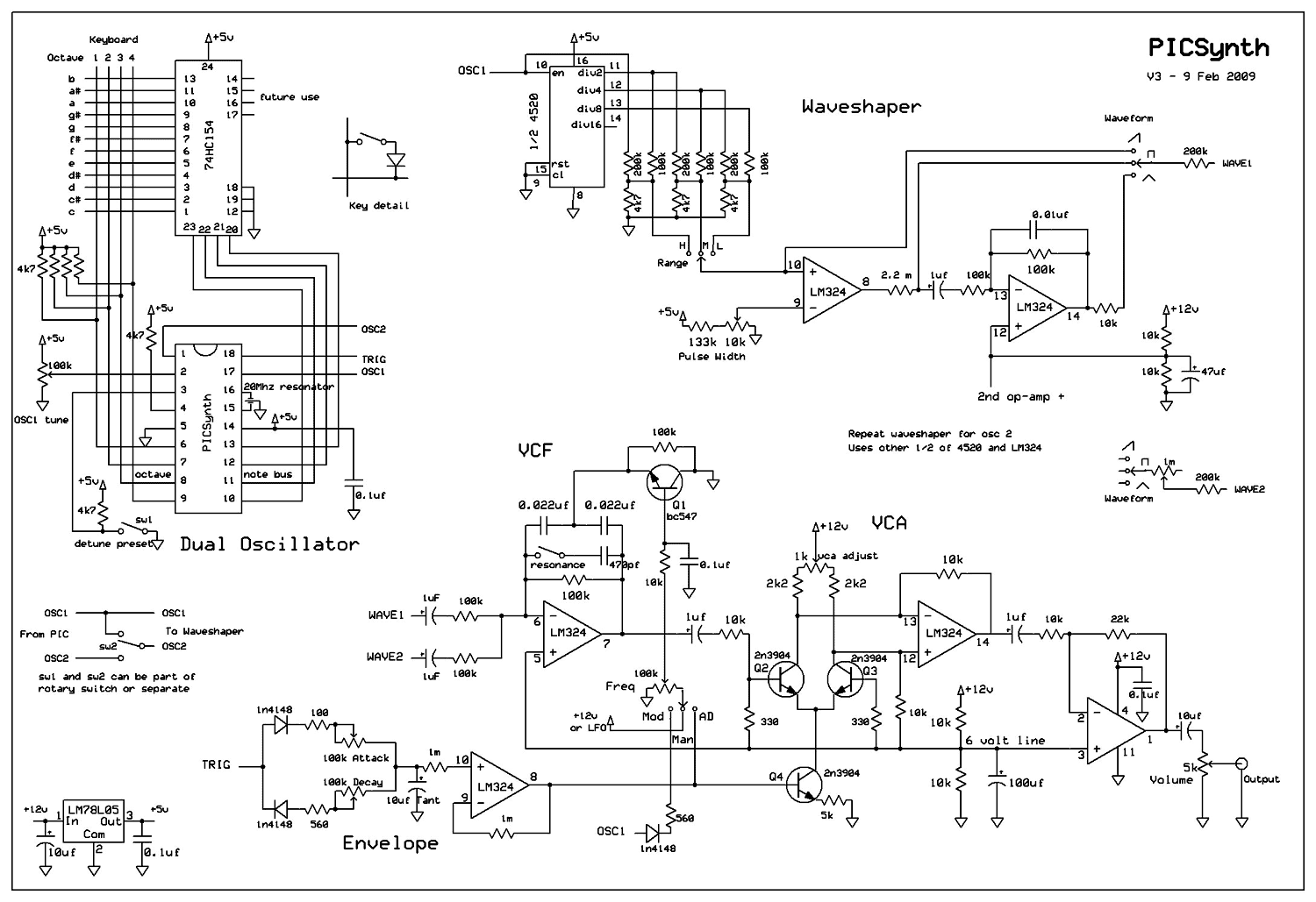
The described analog synthesizer is a dual oscillator mono synth that utilizes a straightforward design, making it accessible for hobbyists and builders with basic electronic skills. The core of the synthesizer is a custom programmed PIC microcontroller, which operates at 20 MHz, ensuring precise timing and control for the oscillators and keyboard scanning. The system employs a 74HC154 decoder to manage keyboard input, allowing for a top key priority scanning method that enhances playability.
The dual oscillators generate three distinct waveforms: sawtooth, square, and triangle. The sawtooth waveform is derived from a stairstep approximation of the square wave, which is further processed through a comparator to create a pulse-width adjustable square wave. The square wave is then integrated to yield the triangle waveform. This flexibility allows for a wide range of tonal possibilities, especially when the oscillators are detuned to create rich, harmonic beats.
The synthesizer also incorporates a voltage-controlled filter (VCF) and voltage-controlled amplifier (VCA), both of which are implemented using a single LM324 quad op-amp and four transistors. The VCF's cutoff frequency can be adjusted manually or modulated by an attack-decay (AD) envelope, providing dynamic control over the sound. The AD envelope also drives the VCA, shaping the overall amplitude of the output signal.
For output, a simple x2 amplifier stage ensures that the final signal is robust enough to drive headphones or line-level inputs, making the synthesizer suitable for both personal use and integration into larger audio setups. The design's modularity allows for future expansions, including the addition of a third oscillator with pulse-width modulation capabilities, further enhancing its versatility.
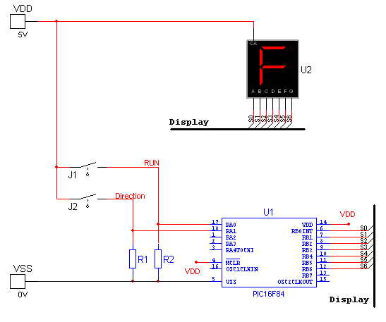
Overall, this synthesizer design exemplifies a balance between simplicity and functionality, making it an ideal project for those interested in exploring analog synthesis. The detailed construction notes, including wiring diagrams for interfacing with salvaged keyboards, provide valuable guidance for builders, ensuring a successful assembly and operation of the synthesizer.A real analog synthesizer to build using easy to get components, capable of a wide range of sounds. The two oscillators can be detuned for that classic synth sound. Dual oscillator mono synth. Really easy to build using just 1 custom programmed PIC chip, 4 ICs and single 12v supply. All circuits built on veroboard - no printed circuit board making skills needed. PIC based dual oscillator and digital keyboard scan. Analog VCF/VCA/Envelope. Waveforms : sawtooth, square (with pulse width adjust), triangle. Fully adjustable detune. Cool Arpeggiator. Portamento. Expandable, first two modules shown below. NEW Option of third oscillator with Pulse Width Modulation. Total cost estimate $89 PIC board, showing 18 pin PIC microcontroller and keyboard decoder.The PIC produces three outputs: two are oscillator outputs, either in-tune or detuned. The other is a trigger output for triggering envelope. The PIC scans the keyboard via 74HC154 decoder using top key priority. The PIC is programmed in assembler for speed and accuracy necessary for producing two oscillators in tune - the chip needs to run at 20 Mhz.
The PDF file contains detailed of how I wired up salvaged Hohner keyboard to the 74HC154. Back of oscillator panel showing waveshape circuit. The dual waveshape circuit divides the PIC square wave into lower octaves (selectable range) and at the same time converts the square wave into an approximation of sawtooth (stairstep). The stairstep is fed into a comparator to produce a pulse width adjustable square wave. The square wave is also integrated to produce triangle. All waveshapes are selectable for each oscillator. Interesting effects can be obtained by mixing different waveforms produced by the two oscillators. If you listen to detunedsaw.wav you should be able to hear the beat of the two oscillators in detune 1 position.
Voltage controlled filter, VCA, Envelope and Output Amp - using a single LM324 Quad op-amp and 4 transistors. The voltage controlled filter cutoff frequency is controlled either manually or follows AD envelope shape.
The AD envelope feeds VCA. Finally a x2 output amp boosts the signal enough to drive headphones or line output. This is just about the most simple VCF/VCA I could build. Other VCF's can be used. I have left 1 position free on the filter voltage source switch for input from a LFO or other modulation source. 🔗 External reference
Related Circuits
In the article you will find a description of the universal PIC programmer, which suggested the involvement of Jens Madsen Dyekjar. Program allows districts PIC12C5XX, 12C67X, 16C55X, 16C61, 16C62X, 16C71, 16C71X, 16C8X, 16F8X, serial EEPROM 24Cxx. It allows to...
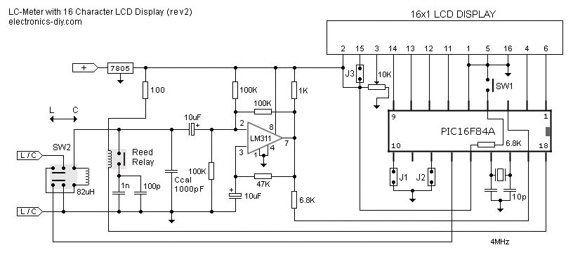
This is one of the most accurate and simplest LC inductance/capacitance meters available, which can be easily constructed by an individual. This LC meter is capable of measuring very small inductances ranging from 10 nH to 1000 nH, 1...
This is a practical expansion board designed for a PIC development board, intended for DIY use with a 16x2 alphanumeric LCD. The expansion board connects to the PIC development board, providing LCD support, which is essential for numerous projects...
This is a lamp timer capable of operating two separate relay switches. Outputs can be in three (or restricted to two) states: OFF, delayed ON and constant ON. Delayed ON mode is indicated by the LEDs. The source code...
National Instruments Multisim now features microcontroller unit co-simulation capabilities, enabling the inclusion of a microcontroller, programmed in assembly or C code, within SPICE-modeled circuits. The MCU functionality in Multisim allows students, educators, and professional users to program MCUs in...
This is an image Schematic. No Description available. The provided input indicates that there is an image schematic without any accompanying descriptive details. In the absence of specific schematics or circuit details, it is essential to consider the typical...
Warning: include(partials/cookie-banner.php): Failed to open stream: Permission denied in /var/www/html/nextgr/view-circuit.php on line 713
Warning: include(): Failed opening 'partials/cookie-banner.php' for inclusion (include_path='.:/usr/share/php') in /var/www/html/nextgr/view-circuit.php on line 713