
PIC Tone generator
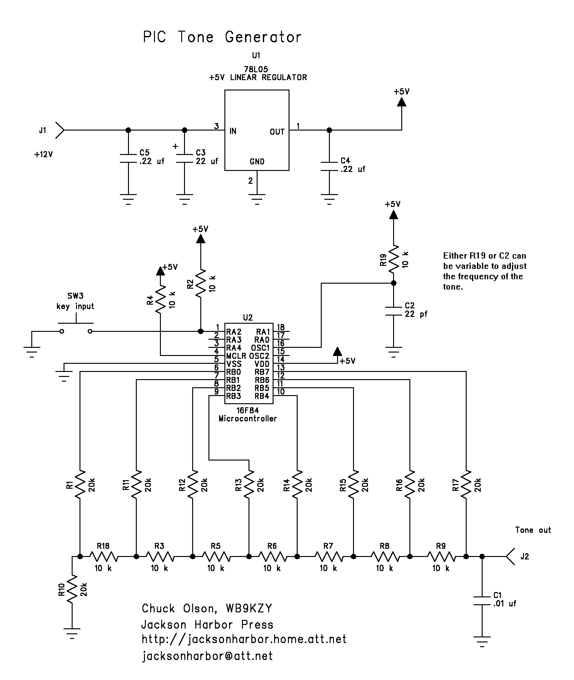
The circuit comprises a PIC16F84 microcontroller, which serves as the central processing unit to control the generation of the sine wave. The PIC16F84 is equipped with a built-in EEPROM, RAM, and a variety of I/O pins, making it suitable for handling the digital-to-analog conversion required for sine wave generation. The microcontroller operates with an RC clock circuit, which consists of a resistor-capacitor combination that can be adjusted using a potentiometer. This adjustment allows for fine-tuning of the frequency of the sine wave output, enabling a range of frequencies to be produced based on user preference.
The 8-bit Digital-to-Analog Converter (DAC) is connected to the microcontroller, translating the digital sine wave samples generated by the PIC into an analog signal. The DAC output is typically connected to a low-pass filter to smooth the output waveform, ensuring that the resulting signal closely resembles a true sine wave.
Input for the tone generation is facilitated through a key or keyer output connected to pin 1 of the PIC16F84. This allows external control of the sine wave output, enabling the user to start and stop the tone generation as required. This feature is particularly useful in applications such as tone generation for communication devices or audio applications where keyed signals are necessary.
Overall, the combination of the PIC16F84, the adjustable RC clock, and the 8-bit DAC creates a versatile circuit capable of generating variable frequency sine waves, suitable for a variety of electronic applications. Proper consideration should be given to the power supply requirements, input/output configurations, and any necessary filtering to ensure optimal performance of the circuit.This program uses an 8 bit DAC along with a 16F84 PIC microcontroller to generate a keyed sine wave. The 16F84 uses an RC clock which can be varied (with a suitable potentiometer) to allow a variable frequency control for the sine wave output. A key or keyer output can be connected to pin 1 of the PIC to control the tone output. 🔗 External reference
Related Circuits
The previous version of this device used pulse width modulation (PWM) to control the power from the five solar panels to charge the battery bank. Under full sun conditions, the MOSFETs got a bit warm and the whole unit...
The schematic of the SAVER V3.2 is depicted in Figure 1. A transformerless power supply uses Xc of a 0.22uF capacitor to limit current, providing about 10mA current source. The diodes rectify AC current to DC current, which in...
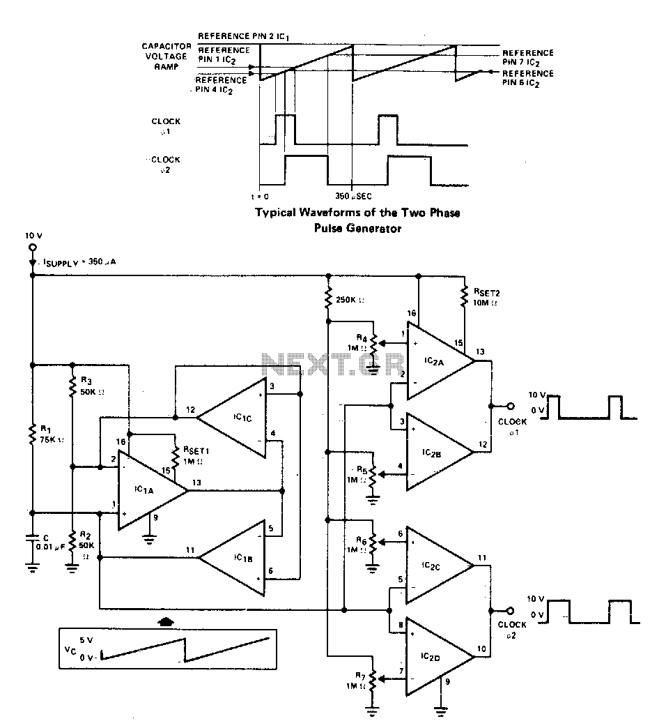
A two-phase clock generator utilizes two L161 integrated circuits to produce pulses with adjustable widths and phase relationships. Additionally, a ramp generator supplies input to two variable window comparators, which are configured using IC2A-IC2B and IC2C-IC2D, respectively. The two-phase clock...
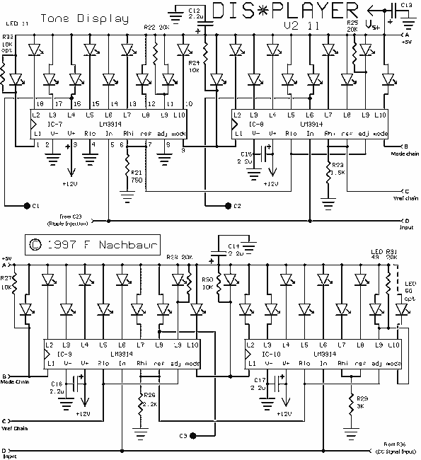
The heart of the circuit is the tone (pitch) display section, based on the popular LM3914 display driver. This device drives ten LEDs in a linear display, with programmable endpoints and the choice of "dot" or "bar" modes of...
On occasions when it is necessary to determine if an amplifier is functioning, the most effective tool is an acoustic signal source with a frequency around 1 kHz. The specifications can be considered flexible, as rapid tests typically do...
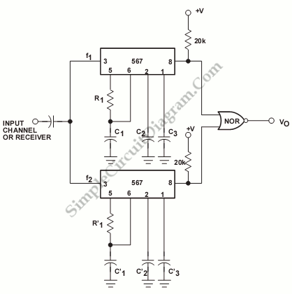
The output of this circuit will be activated when a mix of two tones or frequencies is detected at the input. The frequency, denoted as f, is determined by the values of resistor R1 and additional components. This circuit is...