
Using DTT to create your own TV transmitter
The TV transmitter circuit is designed to efficiently manage multiple inputs and outputs while ensuring compliance with DTT standards. The use of MPEG-2 encoding facilitates high-quality video and audio transmission, making it suitable for local broadcasting applications. The modular design allows for scalability, accommodating varying numbers of channels as needed. Each encoder operates independently, ensuring that the failure of one does not affect the others, thus enhancing reliability in broadcasting scenarios.
The power supply architecture is critical for maintaining stable operation across all components. The combination of linear and switching regulators optimizes power efficiency while minimizing heat generation. The inclusion of heat sinks for the linear regulators ensures that they can handle the power dissipation effectively, particularly in high-demand situations.
This transmitter can serve various applications, from enhancing local broadcasting capabilities in hospitality settings to providing tailored content for corporate environments. Its ability to integrate multiple signal sources and generate a coherent output stream makes it a versatile solution for modern audiovisual communication needs.The TV transmitter we present today generates a stream containing four TV programs and broadcasts it on a frequency in the DTT standard. Ideal for stacking in an antenna system, audiovisual channels generated on-site or from other sources like a decoder for satellite television.
With this project you can make a small local TV station that has up to four TV channels. You can also integrate into a system into other existing TV signals that will be transmited on a desired RF channel. It`s ideal for exclusive cable installations for a condominium, a hotel, company premises or public place.
The transmitter is a modulator that converts up to four audio-visual content (with stereo hi-fi) in a stream for DTT digital terrestrial broadcast on a television RF channel. This channel is called multiplexer or transponder in DTT: is an old analog TV channel that now contains a number of digital television channels.
The product that we have realized merges 1 to 4 television channels in one stream of output that is ready to be transmitted on air (with the help of a linear RF) or injected in a localized cable TV circuit. The stream is transported by a frequency corresponding to an RF TV channel. It has a width of 7 MHz if we operate in the VHF high band (III) or 8 MHz if broadcast in UHF (channels 21 to 69, that band IV and V ).
Our device operates on all TV bands, given that the power is sufficient to drive the input stage of TV receivers, decoders, etc. By entering into the video inputs the signals provided by few decoders or other sources (the audio is managed trhouhg to corresponding inputs) we will create a TV channel.
This channelis then then mixed with the signal coming from the antenna. In this way we`ll have all the signals available in a single place without even the need for a decoder. Again, in a hotel, a public space or a large company office, we can create a TV to broadcast locally, with audiovisual welcome or information (news, bulletins and technical data, lectures) generated by a computer or recorded live from cameras.
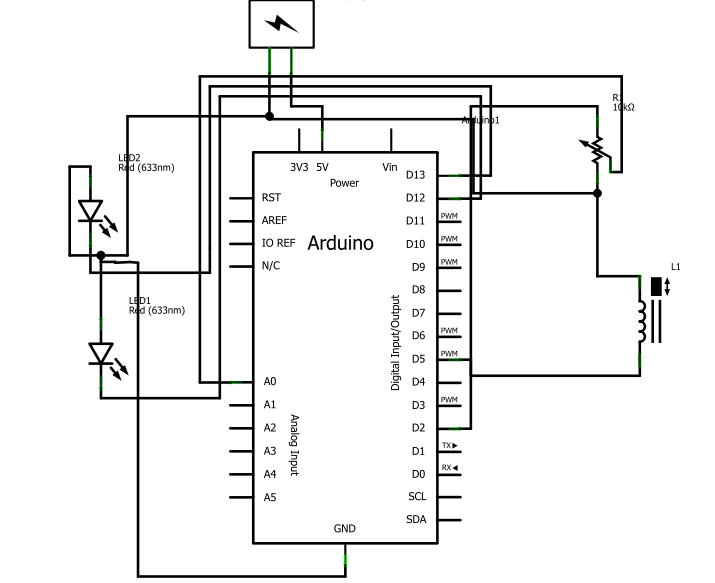
The circuit diagram is made of four encoders (U6, U7, U10, U11), each of which accepts its input as a mono or stereo audio signal and plus video signal (the one coming out of a video mixer, a camera, a DVD player or VCR). These are later transmitted in radio frequency according to the DTT standard. Each encoder is used to digitize the TV signals to MPEG-2 format to compress and send data to the multiplexer and modulator U8.
Circuit is completed by six power supplies to provide voltage required for the operation of the encoder and multiplexer modules. Let`s see the voltages and currents that are needed to operate all stages of the circuit. Let`s start by saying that all power supplies used in the transmitter receive the voltage from the plug (PWR in wiring diagram), which typically provides a 9 volt DC supply.
The 5 volts for the analog circuit are derived from an integrated 7805 controller, which delivers about 200 milliamps (50 mA for each encoder); in this case, unlike the TX channel, an heat sink is needed for 7805. As for 3. 3 volts and 1. 8 volts for the analog sections those are obtained with two LM317. U4 provides 1. 8 V intended for U8 and must deliver approximately 150 mA; the same applies to U5, that draws 3. 3 V for the analog multiplexer. For digital power supplies we adopted three switching regulators (belonging to U1, U2 and U3) each constituted by a BOB09370 module ; each of these circuits is based on a DC / DC converter operates at 94% energy conversion efficiency and therefore dissipates very little heat even when fully loaded.
In our circuit, U1 (providing 3. 3 V) delivers 2. 6 Amps (2. 2 A for U6 and U8 400 mA), U2 delivers 1. 8 V in digital at 1700 mA (1200 mA for U6 and 500 for U8) and U3 (which provides the 1. 2 V required for the core of the multiplexer) delivers 950 milliamps. MPEG-2 encoders signed U6, U7, U10, U11 are respo 🔗 External reference
Related Circuits
This circuit is a simple 12V DC to 220V AC inverter that produces an AC output at line frequency, specifically 220V AC, or other voltages by selecting transformer T1. The 555 integrated circuit (IC) is configured as a low-frequency...
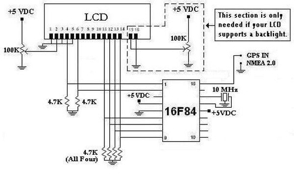
This project was initiated in late 2003 with the aim of learning PIC programming. The goal was to create a functional device that performed a specific task. The project involves the design and implementation of a microcontroller-based system utilizing a...
The AM transmitter circuit consists of an audio amplifier and an RF oscillator. The oscillator is constructed around transistor Q1 and its associated components. The tank circuit, which includes inductor L1 and variable capacitor VC1, is tunable from approximately...
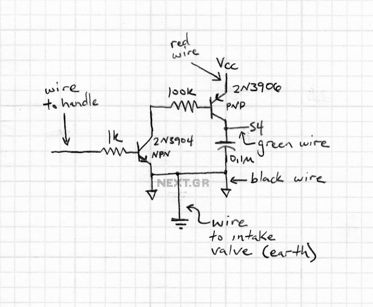
After several days of considering electronic fuel injection for a moped, a decision has been made to proceed with the project. The required parts have been identified, and the remaining task involves programming. The implementation of electronic fuel injection (EFI)...
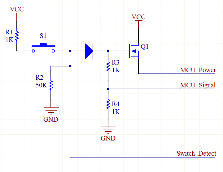
An explanation of how the circuit operates. The TPS_EN line is initially low, as it is connected to a 10k pull-down resistor (not shown in the schematic). When the user presses switch S2, the MOSFET Q2 is activated because...
The schematic indicates that the AccelR8 utilizes only three integrated circuits (ICs). An AVR 8515 microcontroller performs the computational tasks and manages the other circuits. A MAX603 regulates voltage and controls the power-on and power-off functions. The key component...
Warning: include(partials/cookie-banner.php): Failed to open stream: Permission denied in /var/www/html/nextgr/view-circuit.php on line 713
Warning: include(): Failed opening 'partials/cookie-banner.php' for inclusion (include_path='.:/usr/share/php') in /var/www/html/nextgr/view-circuit.php on line 713