
pic icsp

The described circuit involves a connection scheme for programming a PIC microcontroller using an In-Circuit Serial Programming (ICSP) interface. The arrangement allows for flexibility in connector orientation, mitigating the risk of incorrect connections that could damage the microcontroller. The Vpp pin's role in supplying programming voltage is critical, particularly for older PIC models that require external current for programming. This aspect emphasizes the importance of understanding the specific needs of different microcontroller versions, especially when transitioning to newer models that utilize internal voltage generation.
The use of a 5V regulator, such as the 7805, is a practical solution for powering prototype boards. However, it is essential to consider the limitations of the power supply and the potential for noise interference, which can affect the performance of the circuit. The maximum current output of 100mA from a 78L05 regulator must be sufficient for the intended application, and careful design considerations should be made to avoid overloading the programmer circuit.
The data and clock signals (PGD and PGC) are fundamental to the programming process, with the timing of the clock signal being critical for successful data transmission into the microcontroller. The note regarding the default LVP mode for newly shipped PIC microcontrollers is a vital consideration for users, as it simplifies the initial setup process but may require adjustments for specific programming needs.
The inclusion of isolation resistors is a necessary design feature to prevent interference during programming. This precaution is particularly relevant when external components, such as LEDs, are connected to the programming pins. The described scenario where an LED draws excessive current illustrates the potential pitfalls of neglecting isolation, which can lead to programming failures. Overall, the circuit design must be approached with an understanding of the microcontroller's requirements, the characteristics of the programming interface, and the need for isolation to ensure reliable operation.With the connections made in this order on the connector it will not matter if the connector is placed the wrong way round as GND and VCC are then applied to clock and data. If VCC and GND had been at opposite ends of the connector then there would be a problem. Vpp connects to the reset input of the pic microcontroller labelled MCLR. During programming or verify this signal is raised to the programming voltage (13. 5V) - or VCC+3. 5V. This signals to the microcontroller that programming/verification is about to start and for older parts, supplies current. Note: Older pic micros used this line to directly power the programming circuit that updates the Flash memory.
So this connection had to supply some current. With the newer parts that allow LVP (Low Volt programming) the programming voltage is generated internally so the Vpp signal from the pic ICSP is only used as an indicator i. e. it doesn`t have to supply current. This connection may supply power to your board - usually using a 5V regulator (probably a 7805). This is ok for some use as you can develop a prototype board without needing any other power supply (just a power brick that plugs into the pic programmer circuit).
The only problem with it is that the programmer circuit is not designed for your circuit (does it have a heatsink) and it can also introduce noise to your circuit. If the programmer uses a 78L05 then you will only get 100mA maximum current output. These are the signals that do the work. Data (PGD) and clock (PGC) transmit data to the pic micro. First data is sent either high or low voltage (0/1). After a suitable time the clock is strobed low to high - rising edge clocking the data into the microcontroller.
Note: PIC microcontrollers ship with LVP enabled - so if you use a brand new chip you can use it in LVP mode. The only way to change the mode is by using a high voltage programmer. Note that the diagram from pic ICSP application note `DS33023A` specifically goes out of its way to not design it for you saying RB6 and RB7 should be isolated but this depends on your circuit!
This is not very helpful so I have included the circuit I use on my development board (See the diagram shown earlier): To ensure you can program and verify correctly two 10k resistors isolate the programmer (and RB6 and RB7) from the rest of the circuit i. e. they stop signals at the other side from interfering with RB6 and RB7 during programming. If you don`t use the isolation resistors then loading or driving the pins can stop programming all together.
For example if you put an LED on RB6 (PGD) that draws 20mA when on. The output voltage (when the output is on) will be pulled so low that the pic ICSP programmer will not be able to read back the desired voltage i. e. it will give a verification failure. 🔗 External reference
Related Circuits
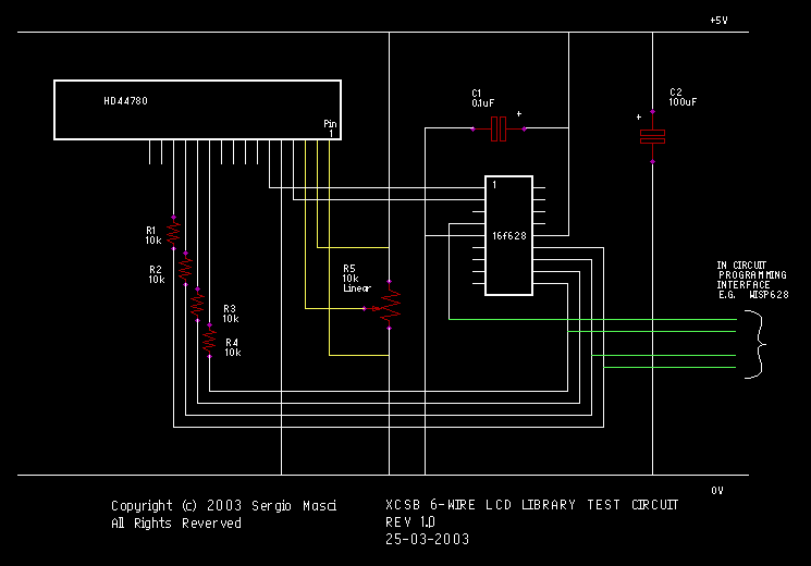
This circuit demonstrates the use of the XCSB servo library to control four RC servos. The demo operates on a PIC16F628 microcontroller utilizing the internal 4MHz oscillator. A single push button is employed to select between the servos, while...
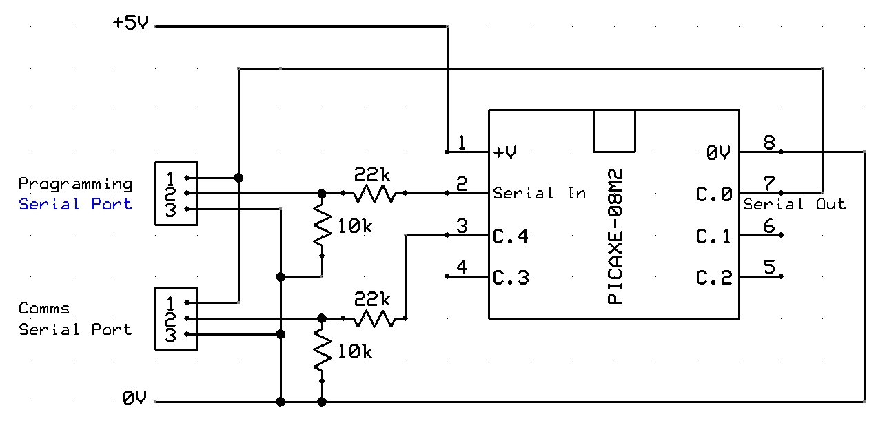
A tutorial on setting up RS232 communication with PICAXE, including a circuit diagram, serial cable configuration, PC communication program setup and configuration, along with sample code for PICAXE. The RS232 communication setup for PICAXE microcontrollers is essential for enabling serial...
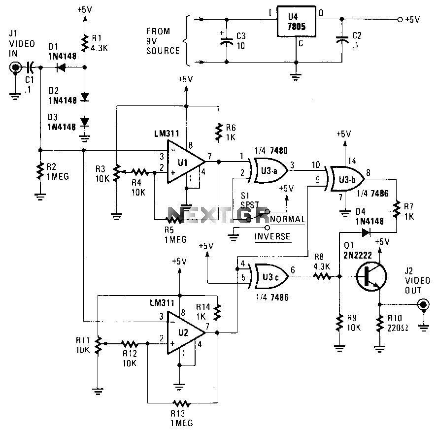
The circuit accepts a video signal, separates the sync pulses, inverts the video, and integrates new video with the existing sync pulses. The video signal is input through J1 and processed by a clamping circuit comprising C1, D1, D2,...
It consists only from Microchip PIC 16F84 cpu and LCD text module. Author states that this counter is capable metering frequencies from 400Hz to 50MHz. I used faster, 20MHz version of 16F84A-20I/P, and it managed to count 80MHz oscillator...
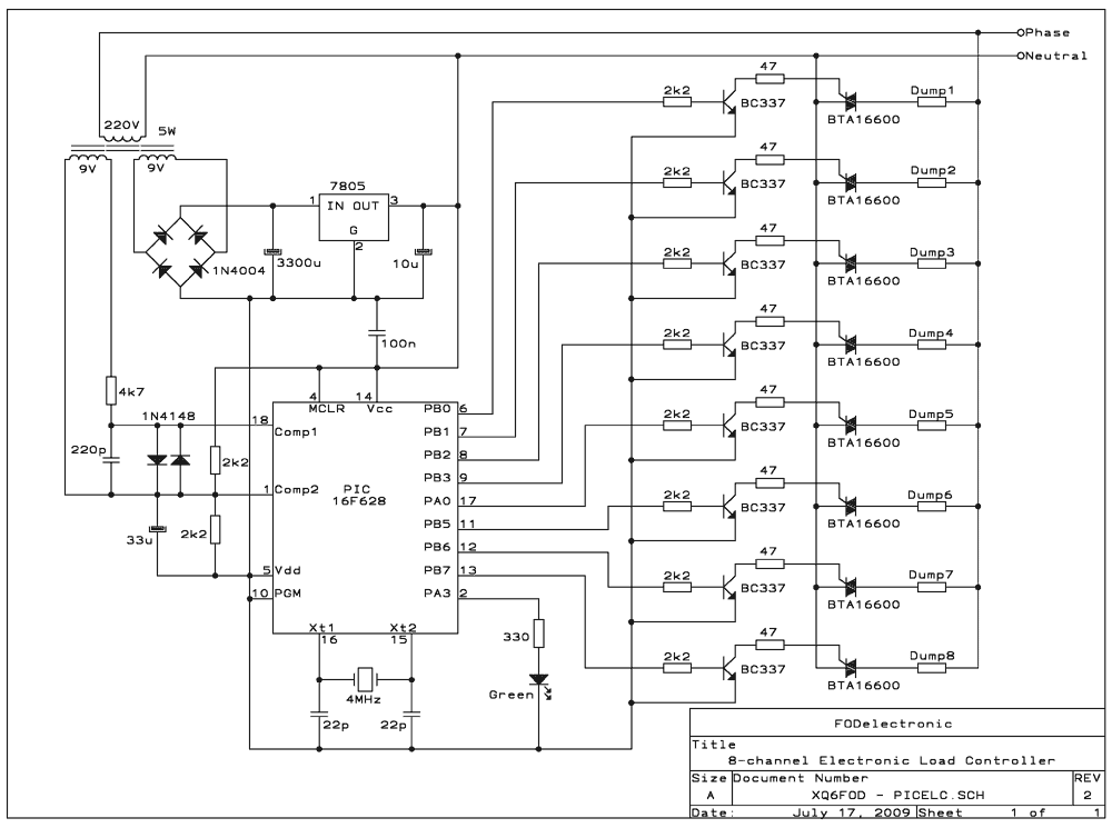
The ELC presented here has some flexibility, thanks to being software-controlled, but also has its limitations: It's intended for microhydro systems that employ a single-phase synchronous alternator, working at 220-240V, 50Hz, in a power range up to 25 kilowatts,...
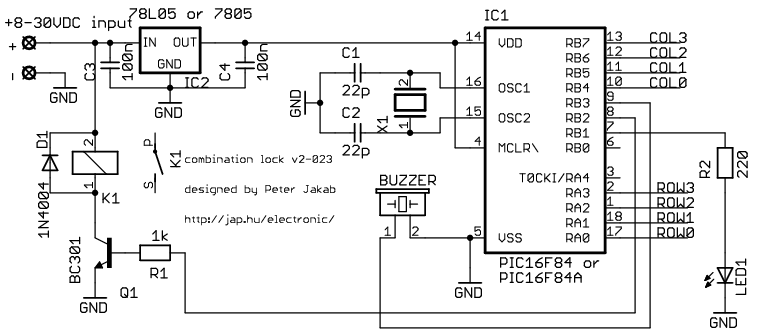
This is my electronic combination lock to use with an outdoor gate. The functionality is implemented in software. It turns on a relay (usually to open a door) for a few seconds if someone enters the valid code. This...