
communicate with the picaxe
The RS232 communication setup for PICAXE microcontrollers is essential for enabling serial data transmission between the PICAXE and a PC or other serial devices. This tutorial provides a comprehensive approach to establishing RS232 communication, covering the necessary components, circuit design, and software configuration.
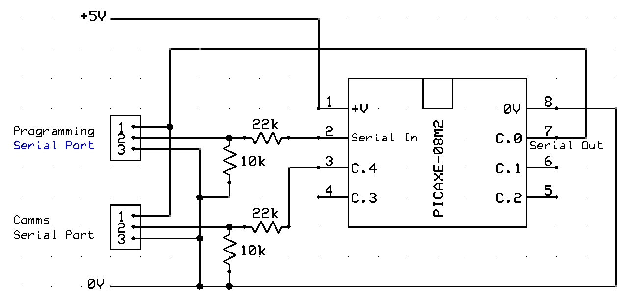
The circuit diagram typically includes a PICAXE microcontroller, a MAX232 level converter, and the necessary capacitors to ensure proper voltage level shifting between the microcontroller and RS232 standard levels. The MAX232 is crucial as it converts the TTL signal levels from the PICAXE to the higher voltage levels required by RS232 devices, and vice versa.
For the serial cable configuration, a standard DB9 connector is commonly employed. The wiring should connect the relevant pins from the DB9 to the MAX232, ensuring that the Tx (transmit) and Rx (receive) lines are correctly aligned. The typical configuration involves connecting the PICAXE’s Tx pin to the MAX232’s Tx output and the Rx pin to the MAX232’s Rx input.
In terms of software setup, a PC communication program such as PuTTY or Tera Term can be utilized to establish a serial connection. The configuration settings typically include selecting the correct COM port, setting the baud rate (commonly set to 4800 or 9600 bps), and ensuring the data bits, stop bits, and parity settings match those configured in the PICAXE program.
Sample code for the PICAXE is essential for testing the communication link. The code should include commands for sending and receiving data via the serial interface, demonstrating how to transmit simple messages or variable data from the PICAXE to the PC. This code serves as a practical example of how to utilize the established RS232 communication link effectively.
Overall, this tutorial provides a foundational understanding of setting up RS232 communication with PICAXE, detailing the hardware connections, software configurations, and example code necessary for successful implementation.A tutorial on setting up RS232 communication to PICAXE with circuit diagram, serial cable configuration, PC communication program setup and configuration and sample code for PICAXE.. 🔗 External reference
Related Circuits
The example circuit is designed for an automatic animal feeder. When the animal activates the switch, the PICAXE microcontroller detects this input. The program within the microcontroller then sends an output signal from pin 6, energizing a relay. This...
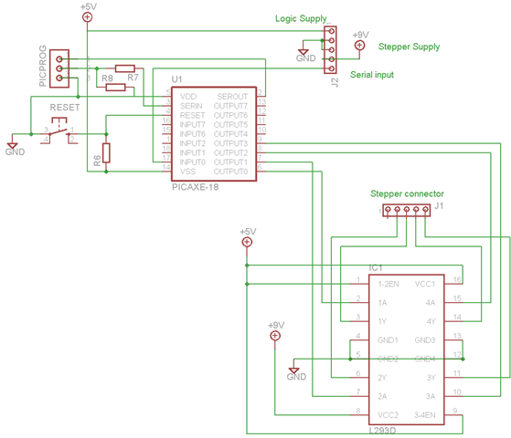
A schematic and program have been developed for operating a bipolar stepper motor through a serial interface, similar to the unipolar configuration. This is significant for the robot arm project, as two of the three stepper motors will be...
Over the weekend, an attempt was made to perform mechanical work by machining acrylic material to create a joint using a stepper motor. The effort was unsuccessful, particularly when trying to score and snap the acrylic, as cutting lengths...
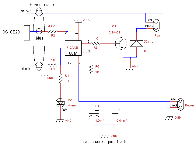
This is a fan controller designed for an audio/video cabinet. It utilizes a PICAXE 08M microcontroller and a DS18B20 temperature sensor. The fan activates at 30 degrees Celsius (approximately 86 degrees Fahrenheit) and deactivates at 28 degrees Celsius (around...
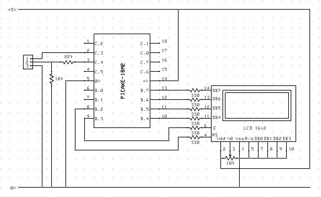
The circuit diagram and code on how to connect a 16x2 LCD to a PICAXE-18M2 microcontroller. The circuit involves interfacing a 16x2 Liquid Crystal Display (LCD) with a PICAXE-18M2 microcontroller. The 16x2 LCD is a popular display module that can...
After working with an LCD, driving LED segments becomes relatively straightforward, so programming should not be a major concern. The 20M circuit mentioned earlier includes code and a schematic. The forum receives various educational inquiries, especially close to submission...