
Advanced Light Dimmer

The following ramp signal generator is quite a simple ramp generator based on discrete transistors which do some switching, a capacitor, and a constant current source made by using one transistor. Besides generating the ramp signal, the sample generator circuit works as a power supply comparator part of the dimmer. The 13.5V unstabilized output is used to power the comparator section (that output can be loaded up to 100 mA). The 10V stabilized voltage is used only for internal use in the ramp generator (that stabilized 10V voltage can be also used for some extra low power circuitry which needs 10V voltage, for example, local dimmer controls if such things are needed). The circuit works so that the comparator output is low when the input voltage is higher than the ramp voltage. When the ramp signal voltage gets lower than the input voltage, the comparator output goes high which causes current to start flowing through the resistor to the optocoupler, which causes the triac to conduct. Because the ramp signal starts at every zero crossing from 10V and goes linearly to 0V at the time of one half cycle, the input voltage controls the time when the triac is triggered after every zero crossing. This effectively means that the control voltage controls the ignition phase of the triac. The output of the comparator is a pulse width modulated signal synchronized to mains voltage. The start of every PWM pulse changes the position depending on control voltage, and the end is at the zero crossing of mains voltage. The start of the pulse is used to trigger the output triac. The triac card contains four controlling circuits similar to the circuit shown above fitted into one circuit board (provided by Velleman). Each output channel triac needs its separate small heatsink to be able to handle full 4A current (around 1A maximum without heatsink). Those heatsinks are not allowed to touch each other unless they are isolated from the triac case (in my prototype they were not).
Each output is protected with a 4A fuse, which should be of the fast type to provide at least some kind of protection to the triac against overload. Please note that even a fast fuse does not make this output short-circuit proof, so if a short occurs, it is likely that both the triac and the fuse will be lost (in some fortunate cases, only the fuse might burn). This part of the circuitry needs its own power supply of 9V for generating the triac trigger pulses. This power supply must be separate from any other power supply in the equipment because one end of this 9V voltage is directly connected to the mains input. Each triac controlling circuitry needs around 50 mA, so a total of around 200 mA is required.
The LED shown in the circuit diagram is wired so that it is visible on the dimmer front channel. It is very useful for monitoring the state of the dimmer channels. The components R5 and C1 make an output filter for the circuit to handle highly inductive loads better than without them. The circuit can be built without them, but this might cause some problems with some inductive loads. Because the dimmer has 4 channels, four of such units are needed. A classical LM324 operational amplifier is very suitable to be used in this project because it has four suitable operational amplifiers in one case. This part of the circuitry is powered from unregulated 13.5V voltage supplied by the ramp card. One ramp generator generates the operating voltage and the ramp signal for all four comparator channels. The ramp generator uses a normal mains transformer which can output at least 200 mA of current because it powers both the ramp generator itself and the voltage comparator circuits. A transformer with internal overload protection (overheating protection fuse) is recommended, so no extra fuses are needed for this transformer. If another type of transformer is used, a suitable fuse should be selected to protect it. In any case, a 200 mA fuse on the secondary would be advisable, and possibly also a primary fuse.This circuit is a real core of the dimmer system. This circuit generates ramp 100 Hz signal which is syncronized to the incoming mains voltage. The ramp signal which is generated will start form 10V and go linearly down to 0V in 10 milliseconds. At the next mains voltage zero crossing the ramp signal will again immediatly start from 10V and go down to 0V.
This same ramp signal is fed to all of the 4 comparators in the dimmer. The following ramp signal generator is quite simple ramp generator based on discrete transistors which do some switching, capacitor and a constant current source made by using one transistor. Besides generating the ramp signal the sampl generator circuit works as a power supply comaprator part of the dimmer. The 13.5V unstabilized output is used to power the comparator section (that putput can be loaded up to 100 mA).
The 10V stabilized voltage is used only for internal use in ramp generator (that stabilized 10V voltage can be also used for some extra low power circuitry which need 10V voltage, for example local dimmer controls if such thign are needed). The circuit works so that the comparator output in low when the input voltage is higher than the ramp voltage.
When the ramp signal voltage gets lower than the input voltage the comparator output goes high which causes that current starts to flow through resistor to optocoupler which causes the triac to cnoduct. Because the ramp signal starts at every zero crossing from 10V and goes linearly to 0V at the time of one half cycle the input voltage controls the time when the triac is triggered after every zero crossing.
This effectively means that the control voltage controls the ignition phase of the triac. The output of the comparator is a pulse width modulated signal is is syncronized to mains voltage. The start of every PWM pulse changes the position depending on control voltage and the end is at zero crossing of mains votlage. The start of the pulse is used to trugger the output triac. The triac card contains four controlling circuits similar to circuit shown above fitted into one circuit board (provided by Velleman).
Each output channel triac needs it's separate small heatsink to be able to handle full 4A current (around 1A maximum withouth heatsink). Those heatsinks are not allowed to touch each other unless they are isolated from the triac case (in my prototype they were not).
Each output is protected with 4A fuse, which should be fast type to give at least some kind of protection to the triac against overload. Pleace note that even a fast fuse does not make this output short-circuit proof, so if you happen to short the output, you quite propably loose both triac and the fuse (in some fortunate cases you might only burn the fuse).
This part of circuitry needs it's own power supply of 9V for generating the triac trigger pulses. This power supply must be separate from any other power supply in the quipment, because one end of the this 9V voltage is directly connected to mains input. Each triac controlling circuitry needs around 50 mA, so you need around 200 mA total. The LED shown in the circuit diagram was wired so that it is visible on the dimmer front channel. It is very useful to monitor the state of the dimmer channels. The components R5 and C1 make an output filter for the circuit to handle highly inductive loads better than without it.
The circuit can be built without them, but this might cause some problems with some inductive loads. Because the dimmer has 4 channels, you need four of such units. A classical LM324 operational amplifier is very suitable to be used in this project, because it has four suitable operational amplifiers in one case. This part of the circuitry is powered from unregulated 13.5V voltage supplied by the ramp card. One ramp generator generates the operating voltage and the ramp signal for all four comparator channels.
The ramp generator used a normal mains transformer which can output at least 200 mA of current, because it powers both ramp generator itself and the voltage comparator circuits. I relected a tranformer which has an invernal overload protection inside the transformer (overhating protection fuse), so I did not need to add any extra fuses for this transformer.
If you use other kind of transformer, select a suitable fuse to protect it. In any case a 200 mA fuse on the secondary would be a good idea, propably also a primary fuse. 🔗 External reference
Related Circuits
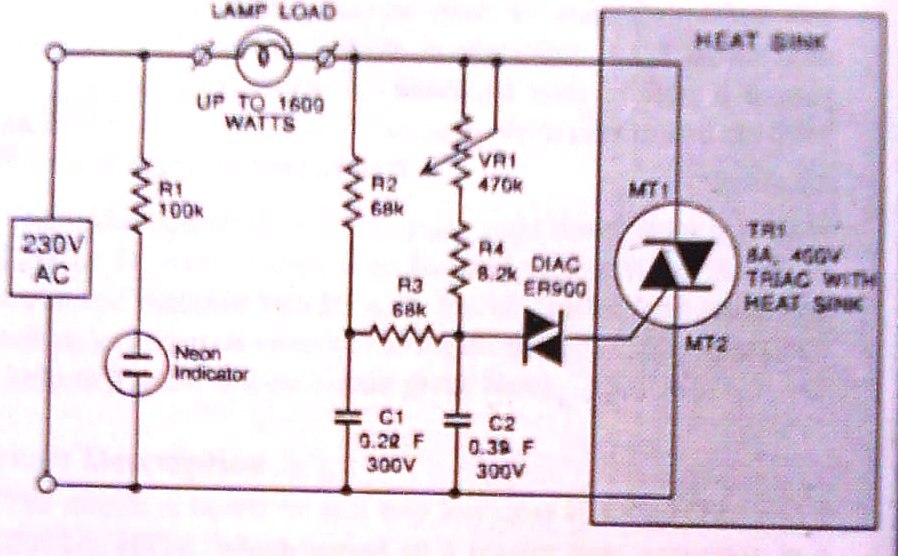
This dimmer is designed to control illumination effectively, with a power handling capacity that exceeds 1600 watts, significantly surpassing the typical 300-watt dimmers. The circuit utilizes a triac rated at 400 PIV and 8 amperes, while component VR1 allows...
A complete guide to addressing challenging electrical system tests in modern vehicles. This resource serves as a comprehensive tool for resolving issues related to the check engine light. Obtain information from a professional technician today. The electrical system in contemporary vehicles...
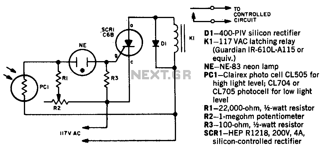
When a beam of light strikes the photocell, the voltage across the neon lamp NE-1 rises sharply. NE-1 turns on and triggers the SCR. K1 is an impulse relay whose contacts remain in position even after the coil current...
Most cars do not have delayed interior lights. The circuit presented can rectify this issue by gradually switching the interior lights of a car on and off. This feature facilitates tasks such as locating the ignition keyhole after the...
A useful operation for the cars is delayed extinguishing internal lighting cabin of passengers, after close some door of car. Certain cars allocate this operation from their constructor. Oldest sure do not allocate such operation. This delay makes this...

This circuit is a simple remote-controlled relay capable of switching lamps or other devices. D1 can be a phototransistor, LDR, or an infrared transistor. The circuit is controlled using an IR remote, similar to a TV remote control, when...
Warning: include(partials/cookie-banner.php): Failed to open stream: Permission denied in /var/www/html/nextgr/view-circuit.php on line 713
Warning: include(): Failed opening 'partials/cookie-banner.php' for inclusion (include_path='.:/usr/share/php') in /var/www/html/nextgr/view-circuit.php on line 713