
PIC Line Follower Robot circuit
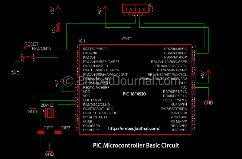
The IR LED and standard LED are similar in appearance, necessitating careful storage to avoid confusion. The fully black component acts as the receiver and must be connected in reverse bias as specified in the circuit. This circuit is relatively simple and does not require extensive explanation; it can be completed as shown.
The comparators are essential in this design. The conduction range of the IR receiver varies with the intensity of infrared light it detects. The line sent to the comparator in the previous circuit provides an analog value (0-5V) based on the IR light incidence. Using Analog-to-Digital Converters (ADCs) for this conversion can be cumbersome. This is where comparators become useful. A comparator compares a reference voltage with the input voltage and outputs a logic HIGH or LOW based on that comparison. Essentially, it converts the analog values into digital values according to a provided reference input.
The line follower circuit employs five IR sensors arranged strategically to enhance tracking accuracy. Each sensor outputs an analog voltage that corresponds to the intensity of infrared light reflected from the line. These outputs are sent to a comparator circuit, which is essential for interpreting the sensor data. The comparators are configured to compare the sensor outputs against a predetermined reference voltage. When the sensor detects a line, the output voltage exceeds the reference, resulting in a HIGH signal, indicating the presence of the line. Conversely, if the sensor does not detect the line, the output remains LOW.
The BeagleBone serves as the central processing unit, interpreting the digital signals from the comparators. It processes the data to determine the appropriate steering commands for the motors, ensuring that the device follows the line accurately. The incorporation of WiFi capabilities allows for potential remote control and monitoring, enabling future enhancements and functionalities.
In summary, the Blackboy line follower represents a versatile and expandable platform for robotic applications. The thoughtful integration of sensors, comparators, and a microcontroller illustrates a well-architected design that accommodates various operational modes beyond simple line following. The potential for modifications enhances its usability in different scenarios, making it a valuable addition to any robotics project.This is a line follower I designed to trace a Grid type tracks, It has 5 line sensors to track the line. This five sensor arrangement is quite good; I have used it a couple of times with good results. This I call it the balckboy. It has a Beagle Bone sitting on top of it adjacent to the 20×4 LCD display. I added the Bone to control black boy through WiFi (you can see a WiFi adapter connected to it even then though the WiFi control is still a future plan :-) ) This I can call the best hardware design I have ever achieved.
It was built with such foresight that it is no longer just a line follower. That was probably the reason behind the fact that it has a name the others don’t :-) It can be modified to work as a edge detector or a wall follower or a maze solver. I will publish a separate post on blackboy some time later.
The IR LED and the normal LED are both similar and can easily be mixed up so be careful when you store them. The fully black one is the receiver and it has to be connected in reverse bias (see the circuit). This is a fairly simple circuit and I don’t think It need much explanation. Go ahead and complete the circuit as it is. 2. The Comparators: I forgot to tell you before, the range of conduction of the IR Receiver varies with the variation the intensity of Infrared light falling on it in other words, the line sent the comparator in the previous circuit returns an analog value (0-5v) depending on the IR incidence.
It’s going to be obnoxious to use ADC’s to convert them into digital. This is when a comparator comes in handy. A comparator is a device that compares a reference voltage with the input voltage and return logic HIGH or LOW based on the comparison. In short, it converts the analog values into digital values based on a reference input given to it.
🔗 External reference
Related Circuits
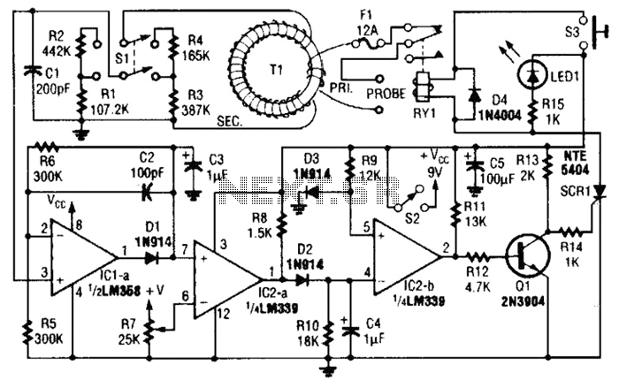
This circuit is an adjustable electronic circuit breaker that features a toroidal transformer designed to sense a 60-Hz load current. The transformer, labeled as T1, has a two-turn winding for the primary side and 100 turns of #30 gauge...
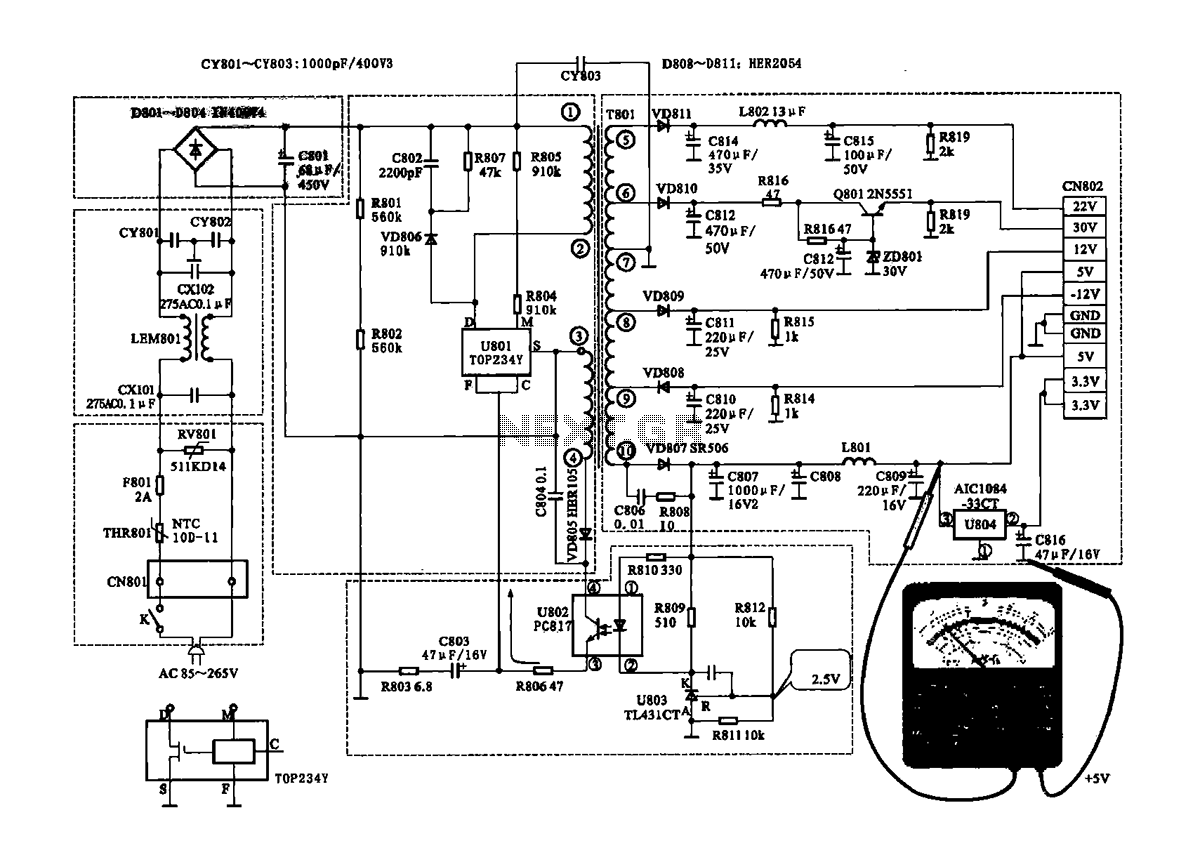
The Coship CDVB3188V receiver features a switching power supply circuit similar to the CDVB3188C model. The circuit includes several key components: an AC input circuit, an anti-jamming filter circuit, a complete flow filter circuit, and a switching oscillation circuit....
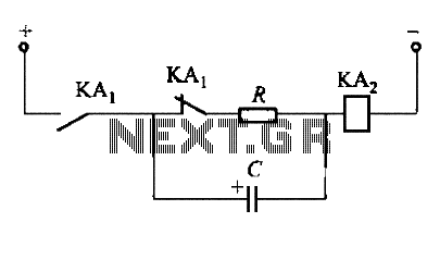
To fulfill the requirements of a control loop, it is often necessary to utilize an electromagnetic relay or a transistor relay to either accelerate or delay an action, thereby forming an acceleration or delay circuit. The circuit depicted in...
This project is suitable for individuals who enjoy experimenting with electronics. It presents a low risk of damaging the unit. This project involves creating a simple electronic circuit that allows users to engage in hands-on experimentation without significant risk. The...
This circuit includes a 2048 radio remote control transmitter and a corresponding wireless receiver that features high reception sensitivity and low power consumption. The combination of these two components provides a highly reliable remote control system, suitable for various...
This circuit utilizes a photoelectric coupler to achieve 100GΩ isolation between a TTL (Transistor-Transistor Logic) circuit and a relay circuit. This configuration effectively prevents relay noise and peak voltage from affecting the TTL circuit. When the TTL input signal...