
Night Light Saver V3.2 (PIC12C508)
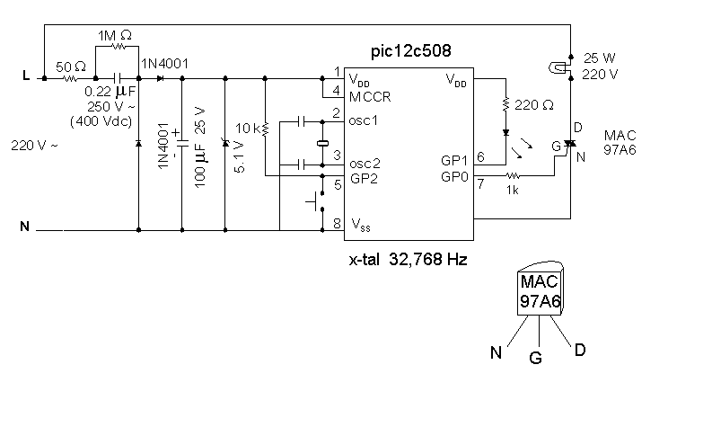
The SAVER V3.2 schematic is designed to operate as a compact and efficient circuit for low-power applications, particularly suitable for microcontroller-based projects. The transformerless power supply is a critical feature, utilizing a 0.22μF capacitor that acts as a reactance element to limit the current drawn from the AC mains. This configuration allows the circuit to draw approximately 10mA, which is adequate for the operational requirements of the microcontroller without the bulk and weight of a transformer.
The rectification of the AC voltage is performed by a pair of diodes, which convert the AC input into a pulsating DC output. The output is then smoothed by a 100μF filtering capacitor, which helps to reduce voltage ripple, ensuring a stable DC supply for the subsequent stages of the circuit.
To regulate the output voltage to a stable level suitable for the microcontroller, a 5.1V zener diode is employed. This component clamps the voltage to approximately 5V, which is the operating voltage for the PIC12C508 microcontroller. The zener diode's role is crucial in protecting the microcontroller from voltage spikes and ensuring reliable operation.
The microcontroller itself is powered by a low-frequency 32kHz crystal oscillator, which provides the necessary clock signal for the PIC12C508. This choice of frequency helps to minimize power consumption, making the circuit suitable for battery-operated applications or where energy efficiency is paramount.
The circuit also features a momentary button connected to the GP2 pin of the microcontroller. This button serves as an input for setting the time to 8:00, allowing user interaction with the device. The simplicity of the button interface facilitates straightforward operation, which is essential for user-friendly designs.
Overall, the SAVER V3.2 schematic exemplifies an efficient approach to low-power design, integrating a transformerless power supply, rectification, voltage regulation, and user interface in a compact form factor.The schematic of the SAVER V3.2 is depicted in Figure 1.A transformerless power supply uses Xc of a 0.22uF capacitor to limit current providing about 10mA current source. The diodes rectifies ac current to dc current which in turns charged to filtering capacitor, 100uF. A 5.1V zener diode provides dc supply ~5V to the PIC12C508. The microcontroller circuit runs with low power 32kHz X-tal. GP2 connects a momentary button for setting time to 8:00. 🔗 External reference
Related Circuits
A post related to a do-it-yourself project for creating a VU meter and homemade rhythm lights that are easy to assemble. The project involves designing and constructing a visual audio level meter (VU meter) that responds to sound levels, as...
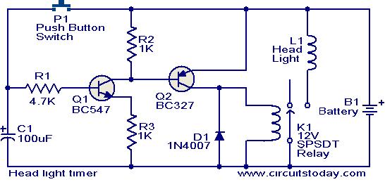
This circuit is a compact timer that keeps the headlights of a car on for approximately 1.5 minutes before turning them off. Incorporating this circuit into a vehicle allows access to dark areas without the need to return and...
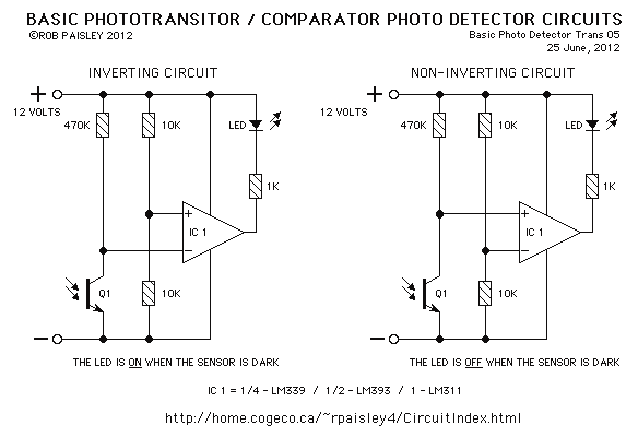
The sensors used are silicon phototransistors and Cadmium Sulfide (CdS) photocells. Both of these sensors allow less current to flow when they are dark than when lighted. Phototransistors change their conductance while photocells change their resistance depending on the...
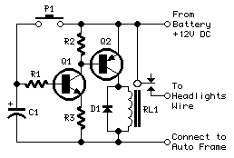
This device is a simple timer that keeps the headlights of a vehicle illuminated for approximately 1 minute and 30 seconds. This feature is particularly useful when accessing dark areas, eliminating the need to return to manually switch off...
This circuit operates at potentially lethal 220V AC mains voltage. The circuit should be built and used only by individuals who know how to safely work with such dangerous voltages and how to construct the circuit to ensure safety....
A 200W lamp switch control operates at a power supply voltage of 220V. It automatically turns the light on or off based on ambient illumination levels, specifically activating at approximately 100 lux. In low light conditions, a time-sensitive resistor...