
Low energy consumption audio signal generator
The described circuit serves as a simple yet effective oscillator for testing amplifiers, particularly in situations where speed is essential and precision is less critical. The Wien bridge oscillator configuration is well-suited for producing a stable sine wave at the desired frequency. The use of an operational amplifier such as the TLC271 allows for a compact design with minimal external components. The voltage divider arrangement ensures that the operational amplifier operates at optimal biasing conditions, facilitating consistent performance.
The choice of diodes for output signal limitation is crucial, as it helps protect the connected amplifier from potential damage due to excessive voltage levels. The noted distortion, while higher than ideal, remains acceptable for basic testing scenarios, where the primary focus is on functional verification rather than audio fidelity. The incorporation of a potentiometer for gain adjustment further enhances the circuit's versatility, allowing users to tailor the output level to suit various amplifier sensitivities.
In summary, this circuit provides a practical solution for quick amplifier testing, balancing simplicity, cost-effectiveness, and functionality. Its design is particularly advantageous for hobbyists and professionals who require a reliable method for ensuring amplifier operation without the need for intricate setups or high-precision instruments.On those occasions when we want to see if an amp works, the best tool we can use is a source of acoustic signal with a frequency around the 1 kHz. These characteristics can be merely 'tolerated', because in cases of rapid tests rarely consider whether the amplifier is quality.
We need only find that it works So, the deformation of the generator is a parameter without irrelevant, giving way to another more important: consumption. The design of the circuit discussed below has been done so that the generator is to fulfill the above requirements.
With prices of (ordinary) materials listed in the chart, it produces audible frequency 899 Hz, with 1 Vrms output level and all retaining its consumption to 20 mA. From a theoretical viewpoint, this minimum absorption power of self-reliance allows 25,000 hours (!) when powered by a battery of 9 V.
From manufacturing point of view, the circuit is based on an operator type TLC271 (IC 1), which in turn controls a typical bridge Wien. The oscillation frequency is defined by C 1, C2 and R 1-R4. The two inputs of an operational kept in force equal to half the supply voltage through the divider formed from A3, A4 and A5, R6.
The latter two resistors is also part of the panel feedback. The gain factor is defined by the grade of P1 on the X3. The diodes 1 and 02 are intended to limit amplitude of the output signal. However, since the characteristic curve is anything but linear, it can be considered is obvious that the signal will be highlighted in the output of step will be distorted. When the generator output 1 Vrms, the value of deformation is about 10%. We reiterate that this course has absolutely no importance to quickly control the amplifier. If however 10% seems too large, you have to join the pin 8 of integrated earth. Such a move would drastically reduce the deformation of 0.7% (with proper settings), but will increase while consumption at 640 Ma.
If for setting you can not use paramorfosimetro, sure to fine tune the output voltage. generator to 1 Vrms. Since the deformation of the generator is high anyway, there is no reason to use in place of C 1 and C2 capacitors sophisticated. Prefer therefore, ordinary (and cheap) ceramic. 🔗 External reference
Related Circuits
Measures 10mV to 50Volt RMS in eight ranges. Simply connect to your Avo-meter set to 50µA range. Connect J2 and J3 to an Avo-meter set to 50µA range. Switching SW2 the four input ranges will be multiplied by 5....
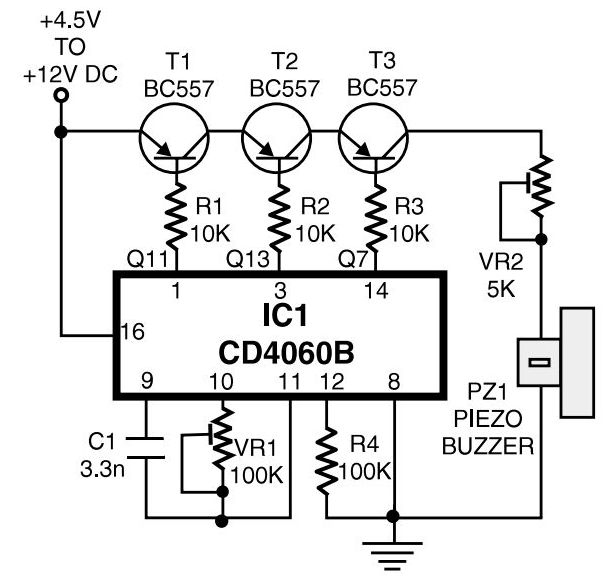
This is a simple home telephone ringtone generator circuit built using only a few electronic components. It generates a simulated telephone ringtone and requires a DC supply of 4.5V to 12V. This circuit can be used in ordinary intercom...
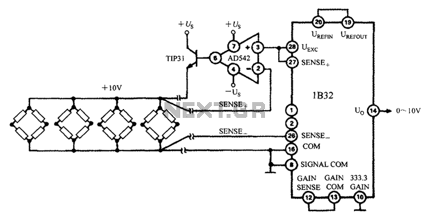
The 1B32 application circuit features multiple pressure sensors as illustrated in the figure. Excitation power is supplied through the AD542, which is followed by a TIP32 transistor that drives multiple bridge sensors. The AD542 operates as a Bi-FET in...
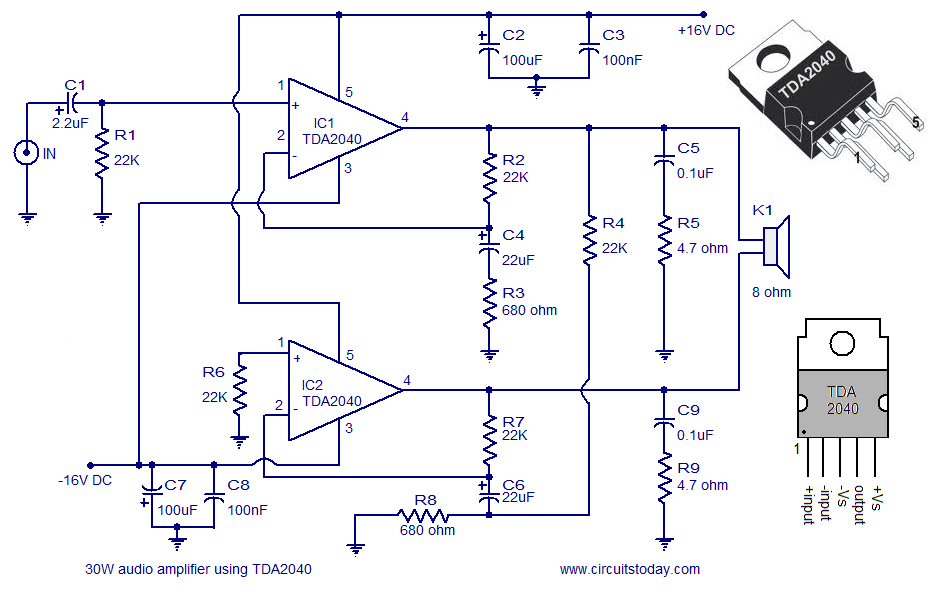
The individual is new to electronics but enjoys experimentation. They plan to create a small guitar amplifier based on a 30 Watt design, specifically the single 12VDC version referenced in comments. The intention is to incorporate a preamplifier to...
When the power supply reaches the circuit and the input signal is applied, the sound signal is processed through capacitor C1 and resistor R1 for signal coupling and noise reduction. The modified signal then reaches pin 3 (non-inverting) of...
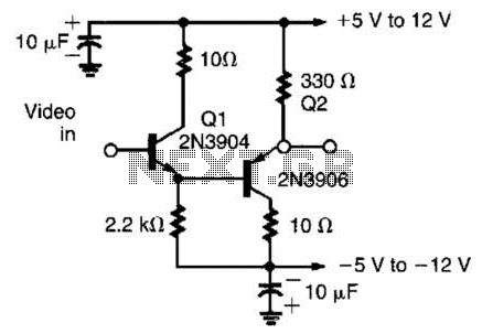
This circuit has demonstrated effectiveness as a video buffer and can easily drive a 75-ohm load to a 1.5-V peak-to-peak output. The bandwidth exceeds 20 MHz, and the DC offset is less than 0.05 V, attributed to the difference...