
Solid state relay circuit with MOC3011 triac driver
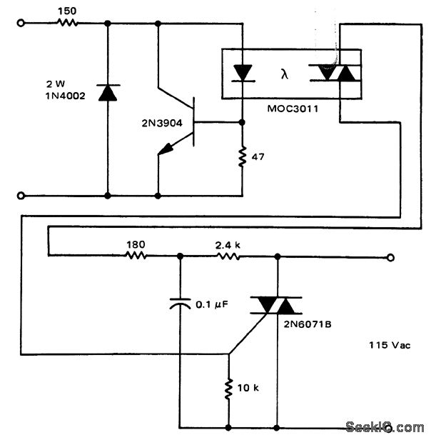
The solid-state relay (SSR) circuit is designed to control high-voltage loads with low-voltage control signals, ensuring electrical isolation between the control and load circuits. The MOC3011 triac driver serves as an essential component in this configuration, facilitating the switching action of the relay while providing input protection.
The circuit operates by receiving a control signal within the specified input voltage range of 3 to 30 volts DC. Upon activation, the MOC3011 triggers the triac, allowing current to flow through the load circuit. This configuration eliminates the need for mechanical contacts, thereby enhancing reliability and longevity.
Input protection is critical in SSR applications to prevent damage from voltage spikes or transients. The circuit may incorporate additional protective elements such as diodes or transient voltage suppressors to safeguard the MOC3011 and the relay from overvoltage conditions.
The output side of the solid-state relay can handle higher voltages and currents, making it suitable for various applications, including industrial automation, lighting control, and motor control. The design ensures that the relay can handle inductive loads, which may generate back EMF during switching, potentially damaging sensitive components.
Overall, the solid-state relay circuit with the MOC3011 triac driver and input protection provides a robust solution for controlling high-power devices with low-voltage control signals while mitigating the risks associated with electrical transients.Solid-state relay circuit with input protection of the MOC3011 triac driver. The input voltage to the protection circuit can be 3 to 30 volts DC (courtesy Motorola Semiconductor Products Inc. ). 🔗 External reference
Related Circuits

The test circuit features a feedback factor of 1/83 utilizing the DA6101Q/6111Q. The input signal is fed through a network comprising resistors R1 and R9, and capacitors C1, C2, and C3, entering the TDA6101Q, which includes three pins for...

For optimal efficiency, set MAX_STEPPERS to the number of stepper motors being controlled, with a maximum limit of four. Motors are identified by indices 0, 1, 2, and 3. On the QCard, there is a trade-off between the number...
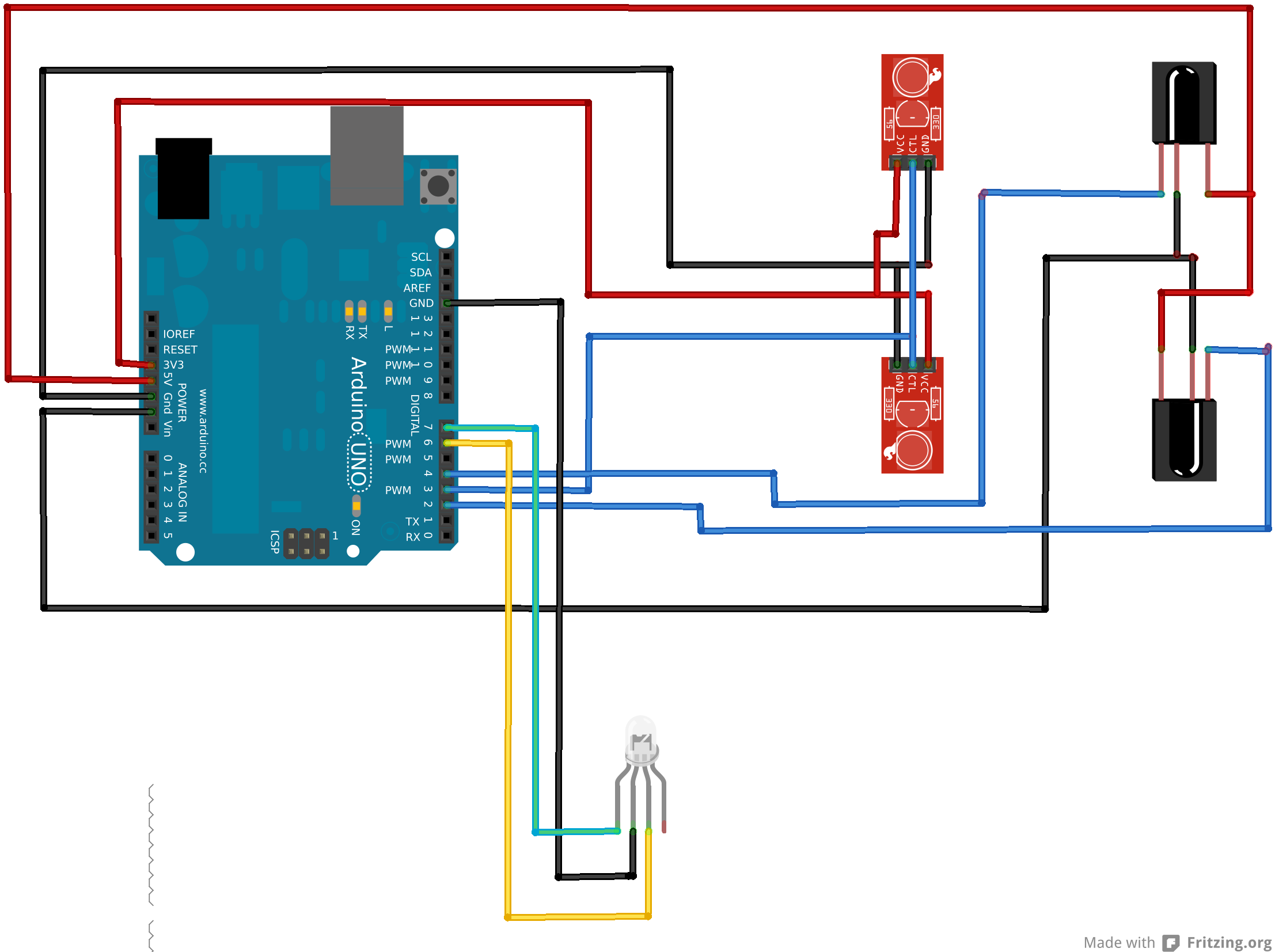
An Arduino Uno is connected to two infrared (IR) transmitters and their respective receivers. When one of the receivers detects a beam break, a strand of LEDs displays a pattern. While this setup functions correctly in principle, an issue...

The automatic fan controller circuit depicted in the schematic features two comparators with distinct triggering points that can be adjusted independently. LM135 or... The automatic fan controller circuit is designed to regulate fan operation based on temperature variations. It employs...
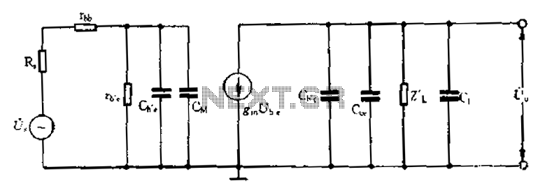
Common emitter amplifier circuit with resistance and capacitance coupling. The common emitter amplifier circuit is a fundamental configuration in analog electronics, widely utilized for its ability to amplify voltage signals. This circuit employs a bipolar junction transistor (BJT) as the...
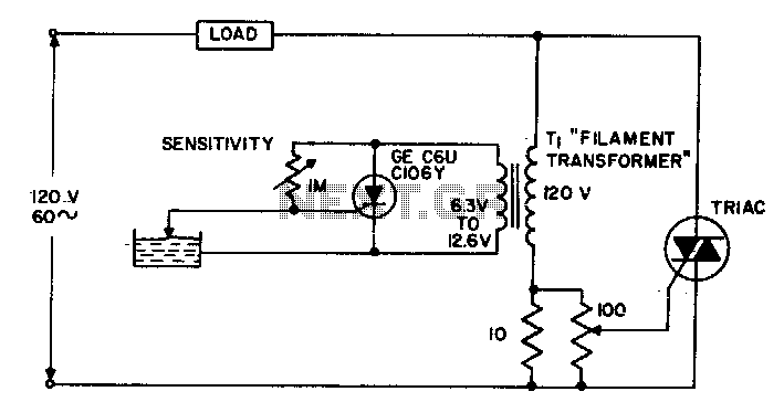
The circuit supplies power to the load until water conducts through the probe, allowing gate current to bypass from the low current SCR. This configuration provides an isolated low voltage probe to meet safety requirements. The described circuit operates as...
Warning: include(partials/cookie-banner.php): Failed to open stream: Permission denied in /var/www/html/nextgr/view-circuit.php on line 713
Warning: include(): Failed opening 'partials/cookie-banner.php' for inclusion (include_path='.:/usr/share/php') in /var/www/html/nextgr/view-circuit.php on line 713