
Single-channel remote control
The circuit design for the single-channel remote control integrates several key components that facilitate its operation. The Nutchip (IC1) acts as the primary microcontroller, responsible for processing remote control signals and executing the desired functions. The radio receiver module (RX1) captures signals transmitted from the remote control and sends them to the Nutchip.
The transistor (TR1) serves as an interface between the Nutchip and the relay, allowing for the amplification of current necessary to energize the relay coil. The relay itself is configured with both normally closed (NC) and normally open (NO) contacts, providing flexibility in controlling various loads. The design ensures that the relay can handle significant voltage and current levels, making it suitable for household applications.
The power supply circuit includes a stabilized 5V source (M1) that is crucial for the reliable operation of the Nutchip and other components. The inclusion of capacitors (C2 and C3) helps mitigate voltage fluctuations and radio frequency interference, ensuring stable performance.
The reset functionality, managed by the RC delay network connected to the RESET pin of Nutchip, allows for a robust response to power interruptions, with the integrated circuit (IC3) providing additional stability during voltage dips.
Diodes (D1 and DL2) are strategically placed in the circuit to protect against back EMF generated by the relay and to provide visual feedback on the relay's status, respectively. The programming connector (CN1) allows for easy uploading of the truth table into the Nutchip, facilitating customization of the remote control functions.
Overall, the project presents a compact and efficient solution for building a single-channel remote control, with careful attention to component selection and circuit design ensuring reliable operation in various applications.In this project we'll see how to build a single-channel remote control. It 's a project easy to do : by using a radio module pre-assembled, we will get a card compact without sacrificing performance major. The insert function allows Nutchip impossible to obtain with a remote commercial: here are some suggestions from our readers.
timer function : with a remote button, the relay remains energized for a time. mixed-function : two buttons switch on and off the relay, the third on for a short time, the fourth for a long time. delay function : By pressing the button on the remote, the LED lights now, but the relay is activated only after some time.
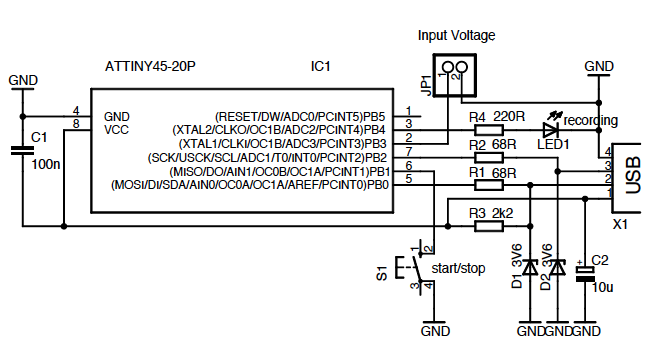
The schematic includes a few components. In addition to Nutchip (IC1) trovialmo rel? a transistor with its pilot (TR1), an LED (DL1), and the radio receiver module (RX1). The ?-RESET pin connected to an external RC delay network driven by a dedicated integrated (IC3), a Motorola MC34064. With this integrated there will be no problems even in case of blackouts or brownouts, when the available voltage on the power supply might be insufficient to bring values ??to the proper functioning of Nutchip, if your application is not critical, or if you can guarantee continuous availability of 5V, then you can omit IC3.
The other terminals of the board need to give the 5 Volt power supply stabilized (M1) and the output relay contacts (M2). On M2 are both normally closed (NC) and one normally open (NO) relay, which basically functions as a switch.
The relay is energized by activating the output OUT4 Nutchip. The transistor TR1 amplifies the current output of the relay moves to the required (up to 50 mA). The guilty must be with a 5 Volt coil and the output contact must have a voltage and current proportional to the load to drive. For example, to light a bulb, 220V and 100W will be adjusted with a relay coil and contacts from 5Vdc to 250Vac 5A.
The handling of household usually needs to add an external contactor or Servorelay great power. For this scheme we have designed a single sided PCB, which you can achieve ein house following the figure. You can also use a matrix board, building the tracks with lengths of copper wire: in fact the pitch used for the disposal of its components is of 2.54 mm and is indicated by squares visible in the picture.
The assembly is not particularly difficult. It should, however pay close attention to the direction of insertion of the components, because there are many who may be exchanged or inserted upside down. For example IC3 is very similar to the transistor TR1, and IC1, the form RX1, the diode D1 and the LED DL1 are symmetrical potentially at risk of being inserted upside down!
For any doubt always consult the page of components. Also careful not to reverse the + and - 5V power supply stabilized, if you will not have disastrous consequences. The capacitors C2 and C3 are used to "clean up" the voltage from any radio interference that dovvessero slip into the receiver and the Nutchip.
The diode D1 protects the transistor from current peaks that are generated on the coil of the relay at the time of dropout. The diode DL2 instead serves as a warning: you turn drive the output OUT1 Nutchip. Usually comes on to indicate the status of the relay, but being driven by a separate output, nothing prevents you to use it regardless!
The data come from the OUT pin of the receiver and enter the pin REMOTE Nutchip, ready to be decoded. You can upload the truth table in Nutchip just before inserting it into the circuit, but we find it more convenient when the Nutchip is already loaded on the card.
For this reason we have included the programming connector CN1. 🔗 External reference
Related Circuits
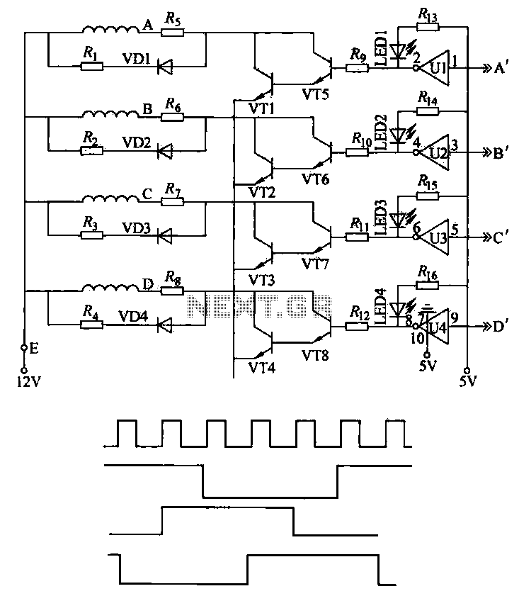
This machine utilizes the FD-CAS-923 1-stepper motor control experiment board with a 4-phase stepper motor to avoid its schematic shown in Figure 4-42a. The JK1 cop 40 core flat cable connector allows for signal arrangements compatible with EICE51 simulation...

The frequency pulses originating from the mains supply are safely insulated by capacitors C1 and C2, along with inductor L1. These pulses are amplified by transistor Q1, while diodes D1 and D2 limit any peak voltages at the input....
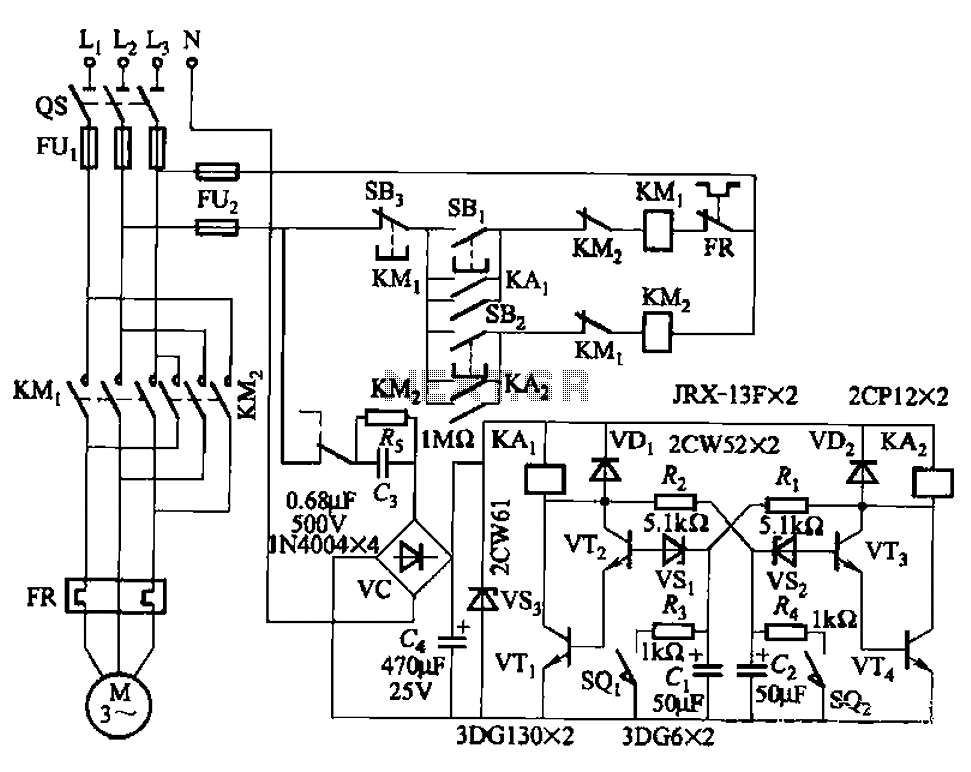
The circuit illustrated in Figure 3-72 employs a deformable bistable reversing motor control mechanism that automatically initiates and halts operation during a user-defined time delay. This feature is designed to safeguard the motor from potential impacts during the reversing...
A wide range frequency meter is a useful tool for an electronics lab. This project describes a frequency meter based on the AT90S231 microcontroller that can measure input frequencies up to 50 MHz. The measured frequency is displayed on...
Early transmitters using LC oscillators experience significant frequency drift. The introduction of Surface Acoustic Wave (SAW) devices addresses this issue, providing substantial frequency stability comparable to crystals. These devices can achieve fundamental frequencies in the hundreds of megahertz or...
This integrated circuit is highly efficient and does not require any external glue logic for operation. It features two pins for motor control: one pin is dedicated to controlling the direction of the motor, while the other pin is...