
PICAXE Infrared Remote Control
The described circuit utilizes a PICAXE-08M microcontroller to facilitate the transmission of infrared signals, specifically designed to send commands via the SIRCS protocol, which is a 7-bit communication standard. The command "TV - mute" is transmitted by configuring the output command to infraout 1, 20, where '1' represents the device address, and '20' corresponds to the specific command for muting the TV. The implementation of sending the infrared signal ten times enhances the reliability of the communication, a technique commonly employed in commercial remote controls to mitigate the effects of signal corruption.
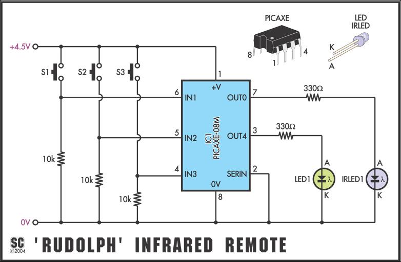
The circuit comprises three push-button switches that allow the user to send different commands, which can be customized to any value between 0 and 127. This flexibility is particularly advantageous for environments where multiple devices are controlled simultaneously, as it prevents command overlap and interference. The inclusion of a second visible LED serves as a user feedback mechanism, indicating when a command is being transmitted.
Assembly of the circuit is designed to be user-friendly, with clear instructions for the installation of components. A wire link is required to be installed at a specified location on the PCB, utilizing an off-cut resistor leg for convenience. It is crucial that the infrared LED is oriented correctly, with its leads bent appropriately to ensure proper alignment and functionality. The circuit is powered by a 4.5V battery pack, with explicit warnings against using incompatible power sources.
For programming, the PICAXE-08M chip must be initially configured on the main Rudolph PC board before being transferred to the transmitter board, as the design does not accommodate a serial link socket. After assembly and programming, the functionality of the infrared transmitter can be verified using a digital camera, which can detect infrared light emitted by the LED, even though it remains invisible to the naked eye. This feature allows for effective troubleshooting and ensures that the device operates as intended. Overall, the project represents a straightforward yet effective solution for remote control applications using infrared technology.To send the Sony command "TV - mute", the command would be infraout 1, 20. Note that device should always be 1 when used in PICAXE projects and data can only be between 0 and 127, as the SIRCS protocol only specifies 7-bit capability. The full program for the transmitter is shown in Fig. 6. As infrared signals are easily corrupted, the data is actually sent 10 times to increase reliability. This matches commercial remote controls that tend to transmit the data at 45ms intervals whilst the button is held down. Note that the program uses codes "1", "2" and "3" for the three switches, but you can edit these to any number between 0 and 127.
This would be useful when you want to control multiple units in the same room, using different data commands for each unit. As hinted at in September, the various tunes played by Rudolph can be triggered remotely using an infrared transmitter.
This simple project uses a PICAXE-08M micro, three push-button switches and an infrared LED to make a complete hand-held remote, the circuit for which appears in Fig. 2. A second visible LED is included for user feedback. Fig. 2: circuit diagram for the simple infrared transmitter. As no serial link socket is provided, the PICAXE chip must first be plugged into the "Rudolph" PC board (described in September 2004) for programming.
Assembly is very straightforward and should only take a few minutes. Begin by installing a wire link in the position indicated by a dotted line on the overlay diagram (Fig. 3). An off-cut resistor leg is ideal for the job. Note that as an IC socket will be mounted over the link, it must be lying flat on the PC board before soldering.
Install the two LEDs next, noting that the infrared LED (IRLED1) leads must be bent at 90 degrees so that it points away from the PC board (see photo). Make sure that you have the flat (cathode) sides of the LEDs oriented correctly. The infrared LED may be supplied in either a "black" or "water clear" epoxy package. Finally, solder the battery leads to the positions indicated after threading through the adjacent hole.
Note that the board runs from a 4. 5V (3 x AA) battery pack do not connect a 9V PP3 battery! To reduce overall size, a serial link socket is not provided on the transmitter PC board. Therefore, the PICAXE-08M chip must be programmed on the main Rudolph PC board and then transferred to the transmitter board. Fig. 3: the overlay diagram for the infrared remote transmitter. Install the wire link (under IC1) first, then all the other parts, making sure that the IC socket is around the right way.
After assembly and programming, you can check transmitter operation by looking at the infrared LED "end-on" through a webcam or digital camera (such as a mobile phone camera). Although the LED is not visible to the naked eye, these camera are sensitive to infrared light and so the infrared LED will display a faint glow on the camera screen whilst operating.
🔗 External reference
Related Circuits

The VCO circuit, which has a nonlinear transfer characteristic, will operate satisfactorily up to 200 kHz. The VCO input range is effective from V% Vcc to Vcc - 2 V, with the highest control voltage producing the lowest output...

This is a three-mode lamp dimmer circuit with touch control. This circuit can be used to control a lamp in three operation modes: dim, off, and bright. It utilizes a NE555 timer. The three-mode lamp dimmer circuit designed with touch...
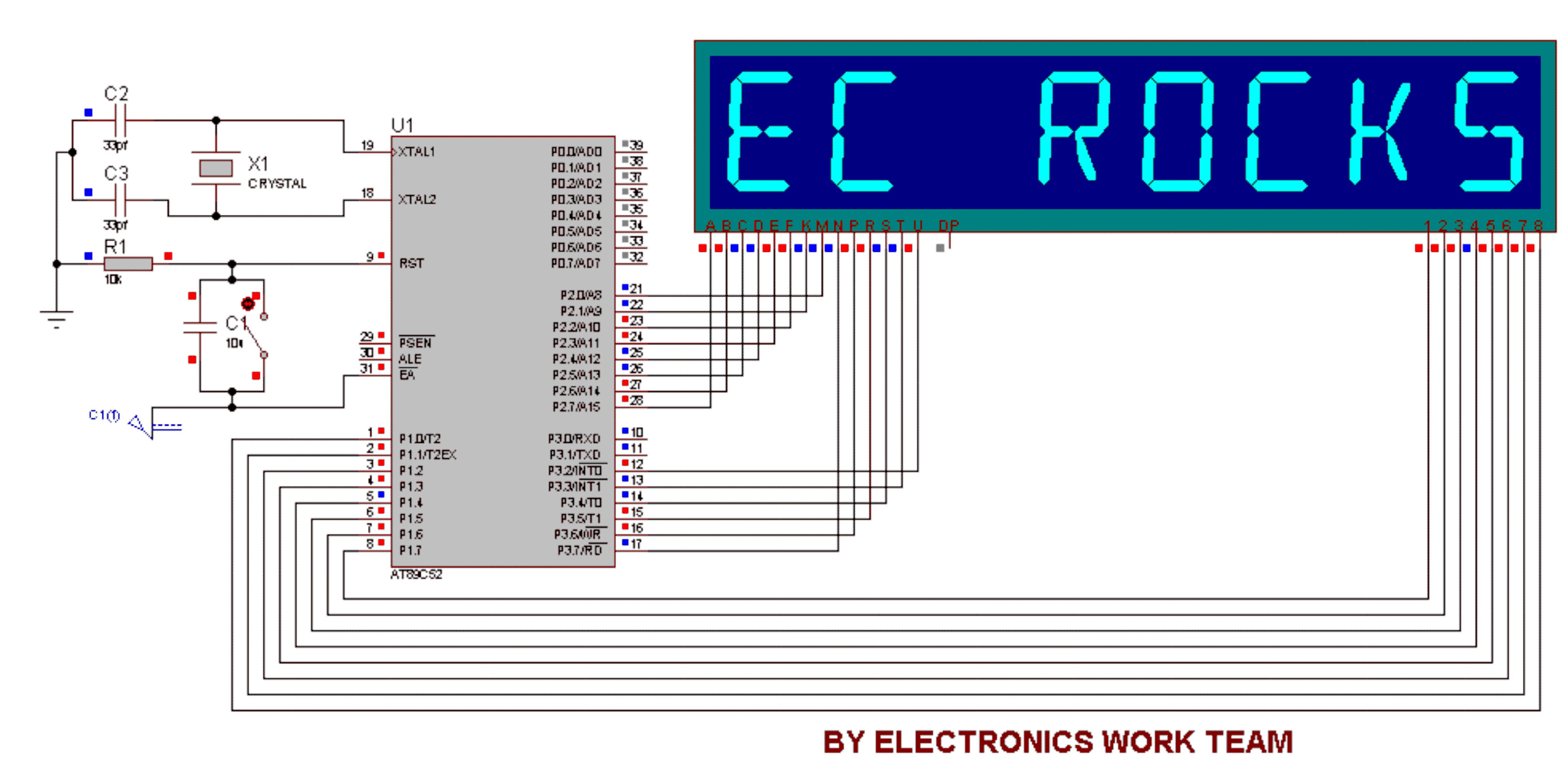
This circuit utilizes a 14-segment display to represent characters. The 14-segment display consists of 22 pins, which facilitate the display of various characters. Eight pins labeled A, B, C, D, E, F, K, and M are connected to the...
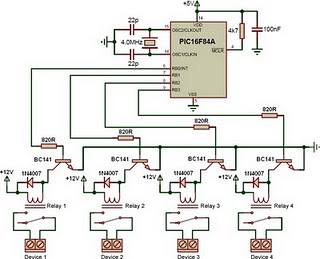
This is a relay driver based on a PIC16F84A microcontroller. The board includes four relays, allowing control of four distinct outputs. The relay driver circuit utilizing the PIC16F84A microcontroller is designed for controlling multiple devices or systems through relay activation....
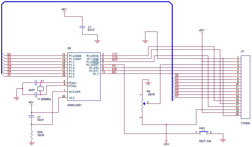
How can graphical LCDs be controlled using a microcontroller? Is there any datasheet available? Graphical LCDs (Liquid Crystal Displays) are widely used in various electronic applications for displaying complex graphics and text. To control these displays with a microcontroller, several...
The dual-channel thermometer is a simple project based on a PIC microcontroller with ADC capabilities. It is an inexpensive thermometer that utilizes low-cost components and does not require high-sensitivity or expensive sensors. Instead, it employs a simple silicon diode...
Warning: include(partials/cookie-banner.php): Failed to open stream: Permission denied in /var/www/html/nextgr/view-circuit.php on line 713
Warning: include(): Failed opening 'partials/cookie-banner.php' for inclusion (include_path='.:/usr/share/php') in /var/www/html/nextgr/view-circuit.php on line 713