
Pico ammeter

The picoammeter circuit is designed to measure extremely low currents with high precision. The amplifier's inverting configuration allows for the conversion of input current to a corresponding output voltage, where a current of 1 picoampere results in a voltage change of −1 volt. This high sensitivity requires careful circuit design to minimize noise and interference, particularly from stray currents that could affect accuracy.
The stabilization time of approximately 5 seconds indicates the circuit's response characteristics, which are critical for applications that involve rapidly changing input currents. During this period, the output voltage will approach its final value, allowing for reliable measurements once equilibrium is achieved.
Protection against voltage transients is a vital aspect of the design. The inclusion of diodes CR1 and CR2 serves as a clamping mechanism, preventing excessive voltage levels from damaging the amplifier's input stage. Resistor R1 works in conjunction with these diodes to limit the current flow during transient events, ensuring that the circuit operates within safe parameters.
Overall, the design considerations for this picoammeter emphasize precision, stability, and protection, making it suitable for applications in scientific research, semiconductor testing, and other fields requiring accurate low-current measurements.A very sensitive pico ammeter (— 1 V/pA) employs the amplifier in the inverting or current summing mode. Care must be taken to eliminate stray currents from flowing into the current summing mode. It takes approximately 5 for the circuit to stabilize to within 1% of its final output voltage after a step function of input current has been applied
The internal diodes CR1 and CR2 together with external resistor Rl to protect the input stage of the amplifier from voltage transients.
Related Circuits
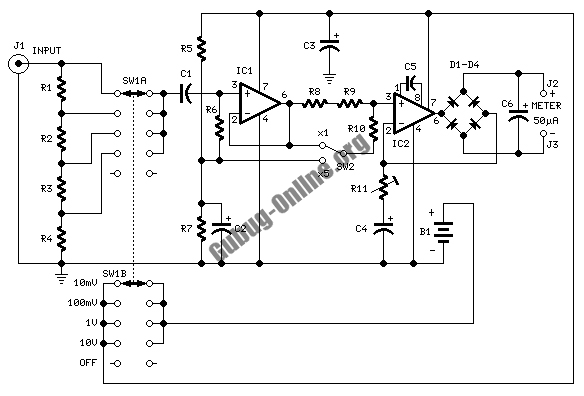
This design circuit is used to activate circuitry and an analog meter for sensitive DC current measurements. A subsequent inquiry raised the possibility of measuring AC microamperes, which inspired the idea for this circuit. The circuit is designed to facilitate...
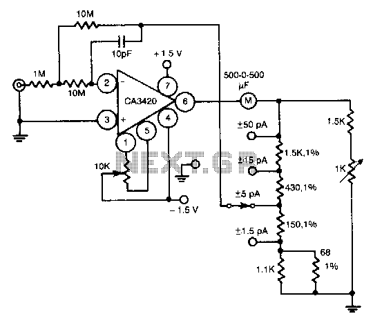
This circuit utilizes the exceptionally low input current of 0.1 pA from the CA3420 BiMOS operational amplifier. It employs a single 10-MΩ resistor. The circuit operates within a range of ±50 pA, achieving a maximum full-scale sensitivity of ±1.5...
This multimeter is designed to measure output voltage and current in a power supply unit (PSU), with the current sense shunt resistor connected in series with the load at the negative voltage rail. It operates using a single supply...
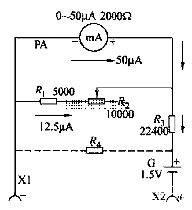
A commonly used high-sensitivity header utilizes a microammeter to create a resistance meter capable of measuring very low voltages. The design adheres to the principles of a milliameter resistance meter. The circuit diagram is illustrated in Figure 5-37, which...
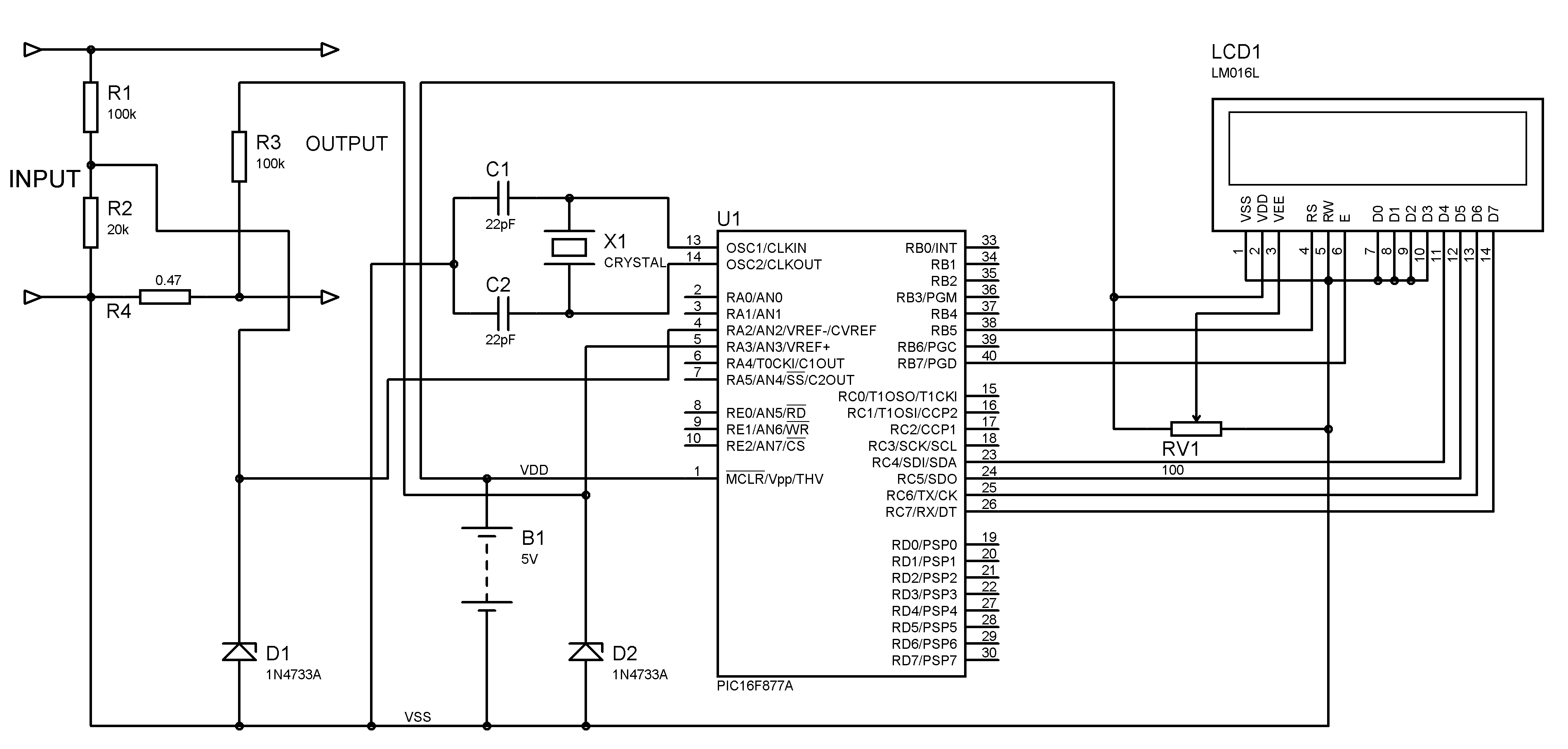
A voltmeter and ammeter can be constructed using a PIC microcontroller equipped with an Analog to Digital Converter (ADC). The project utilizes the PIC16F877A microcontroller, with results displayed on an LCD. This microcontroller is sufficient for testing purposes. For...
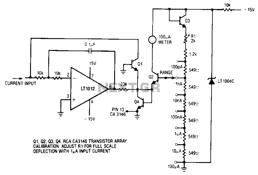
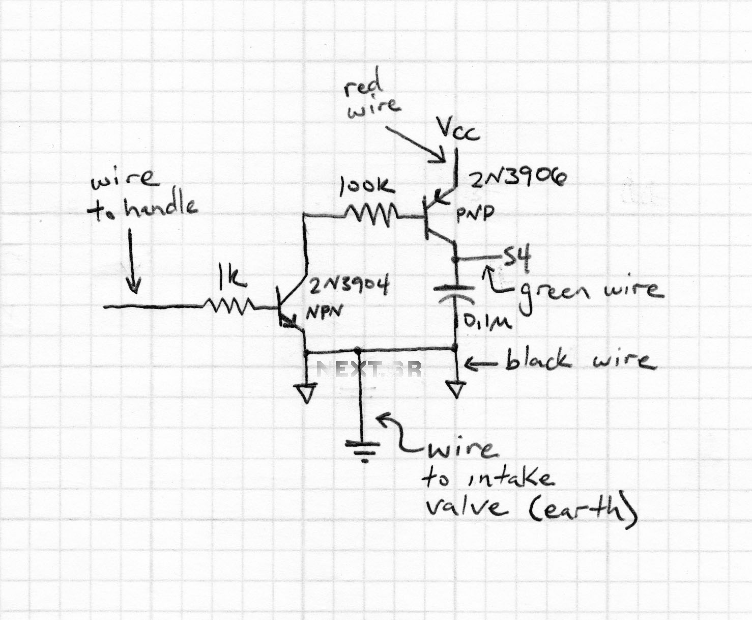
The ammeter measures currents from 100 pA to 100 µA without the use of expensive high-value resistors. Accuracy at 100 µA is limited by the offset voltage between Q1 and Q2, and at 100 pA, it is limited by...