
picpov persistence of vision with a pic18f1220

The PicPOV project utilizes the principle of persistence of vision to create the illusion of a solid image through the rapid blinking of LEDs. The core component of this project is a PIC microcontroller, which is programmed to control the timing and sequence of the LED illumination.
In this circuit, eight LEDs are arranged in a linear format and connected to the output pins of the PIC microcontroller. The microcontroller is programmed to turn each LED on and off at a specific timing interval, synchronized with the movement of the device. When the device is waved through the air, the human eye perceives the rapidly blinking LEDs as a continuous image due to the persistence of vision effect.
The circuit design typically includes a power supply, which can be provided by batteries or an external source, ensuring that the microcontroller and LEDs receive adequate voltage and current. Current-limiting resistors are also included in series with each LED to prevent excessive current flow, which could damage the LEDs.
To enhance the user experience, the message displayed can be pre-programmed into the microcontroller's memory, allowing for flexibility in the designs and messages that can be shown. The programming can be done using various development environments compatible with PIC microcontrollers, enabling the integration of different patterns and sequences.
The overall design of the PicPOV project not only demonstrates the application of microcontrollers in visual displays but also serves as an educational platform for understanding the fundamentals of electronics, programming, and optical phenomena.PicPOV is a project based on ""persistence of vision"". A PIC microcontroller blinks 8 LEDs on and off so that when waved through the air, a mes.. 🔗 External reference
Related Circuits
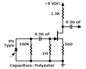
The JFET input configuration is utilized with PN photodiodes, such as the commonly used "bullet cell," which produce extremely low-level signals. Photodiodes provide several advantages over phototransistors, including a faster response to motion and a peak sensitivity within the...

As illustrated in the dividing circuit diagram, A1 consists of a voltage-controlled current source, A2 functions as a voltage comparator, and A3 is configured as an active low-pass filter. When the time constant R1C1 is equal to the clock...

There are several Instructables and other internet-based instructions on how to modify a television set into an audio visualizer or other simple applications. To transform a television set into an audio visualizer, a detailed understanding of both the television's hardware...

An infrared (IR) illuminator designed for night-vision television cameras and scopes. This device employs light-emitting diodes (LEDs) and an astable oscillator to manage the switch, duty cycle, and overall effective IR illumination output. The IR illuminator functions by emitting infrared...
If you have not already read the CT-100 restoration article, it is recommended to start there. It chronicles the discovery of a CT-100 and its restoration to working condition. This article discusses the internal components of the CT-100. After...

The TDA9813T is an integrated circuit designed for processing vision intermediate frequency (IF) signals and dual frequency modulation (FM) demodulation of sound. It operates with a single reference QSS-IF in television (TV) and video cassette recorder (VCR) applications, specifically...