
IR illuminator for night-vision tv cameras and scopes
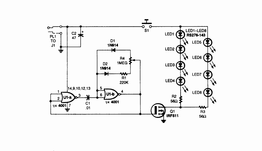
The IR illuminator functions by emitting infrared light, which is invisible to the naked eye but can be detected by night-vision devices. The core component of this system is the array of LEDs, which are selected for their efficiency in producing IR light at specific wavelengths that align with the sensitivity range of night-vision equipment.
The astable oscillator is crucial in this circuit as it generates a continuous square wave signal. This signal is used to drive the LEDs, effectively controlling their on and off states. The duty cycle of the oscillator determines the ratio of the time the LEDs are on versus the time they are off within each cycle. By adjusting the duty cycle, the intensity of the IR illumination can be modulated, allowing for optimal performance depending on the ambient light conditions and the specific requirements of the application.
The circuit typically includes a power supply unit that provides the necessary voltage and current to the LEDs and the oscillator. Additional components may include resistors to limit current, capacitors for smoothing the power supply, and possibly a photodiode or phototransistor to provide feedback for automatic brightness adjustment.
In applications where precise control over IR illumination is necessary, the integration of a microcontroller may be considered. This would allow for programmable settings, enabling features such as varying the intensity based on environmental conditions or user preferences.
Overall, the design of the IR illuminator is focused on maximizing the effectiveness of night-vision systems by providing a reliable and adjustable source of infrared light, ensuring enhanced visibility in low-light conditions.IR illuminator for night-vision tv cameras and scopes. This source uses LEDs and an astable oscillator to control the switch, duty-cycle, and effective IR illumination output 🔗 External reference
Related Circuits

The circuit illustrated in the schematic diagram is a straightforward spectrum analyzer adapter circuit designed for oscilloscopes. This circuit can be utilized for scanning or analyzing signals. The spectrum analyzer adapter circuit is engineered to enhance the capabilities of an...
This circuit was designed for digital cameras, which are known to have significant power consumption. For instance, the Minolta E223 camera requires approximately 800 mA. In practice, this demand can be met using a mains power supply or high-capacity...
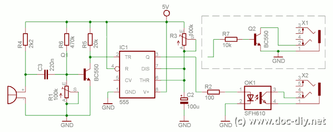
This article describes how to build a simple yet effective sound trigger for cameras or flashes. The circuit allows for experimentation with high-speed photography. The sound trigger circuit is designed to activate a camera or flash unit in response to...

The Clearcom type intercom bus operates at a significantly lower level than the Sony bus. Consequently, the signal sent to the camera operator's headset requires amplification, while the signal from the camera operator's microphone needs to be reduced. To...
Dynamic flip-flops disregard input pulses that are shorter than 40 ns or do not conform to TTL voltage levels. Consequently, TTL flip-flops are not well-suited for certain applications. Dynamic flip-flops are a specific type of sequential logic circuit that utilize dynamic...
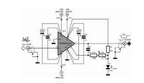
I built this cable for my Casio QV-200 digital camera, it should work for many Casio models. It's basically an inverting buffer/converter to/from RS-232 voltage levels from/to CMOS levels. Why Casio didn't put this inside the camera like everyone...