
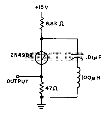
Pierce harmonic oscillator 100Mhz

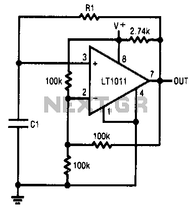
The current meter is designed to accurately measure low currents ranging from 100 picoamperes (pA) to 3 milliamperes (mA), providing versatility for various applications in electronic measurement. The input voltage levels are carefully calibrated, starting at 100 microvolts (µV) for the lowest current range and scaling up to 3 millivolts (mV) at the highest current measurement. This ensures that the meter can detect minute changes in current without introducing significant noise or error.
The inclusion of buffers on the operational amplifier (op-amp) serves a critical function by isolating the measurement circuit from the load, thus preventing any potential loading effects that could distort the readings, especially under high-current conditions. This design choice enhances the reliability and accuracy of the measurements by maintaining a consistent input impedance.
Furthermore, the capability of the output to drive a digital voltmeter (DVM) or a digital panel meter (DPM) extends the utility of the current meter. This feature allows for real-time display of measurements, facilitating easier interpretation of data. The design can be implemented in various applications, including laboratory measurements, industrial monitoring, and electronic testing, where precise current measurements are essential. The circuit's flexibility and robustness make it suitable for both research and practical field use.Current meter ranges from 100 pA to 3 mA full scale. Voltage across input is 100 µV at lower ranges rising to 3 mV at 3 mA. The buffers on the op amp are to remove ambiguity with high-current overload The output can also drive a DVM or a DPM.
Related Circuits
This CMOS square-wave oscillator utilizes the 4047 multivibrator circuit, suitable for both monostable (one-shot) and astable applications. In the provided configuration, the 4047 operates as an astable multivibrator. The circuit features three outputs from the 4047, with the first...
This simple RC oscillator utilizes a medium-speed comparator with hysteresis and feedback through R1 and C1 as timing elements. The frequency of oscillation is theoretically independent of the power supply voltage. Additionally, the comparator swings to the supply rails...
Will an LC-based oscillator be able to demonstrate performance comparable to crystals under such conditions (possibly in unusual configurations like LC-opamp) so that any energy loss at each stage is recovered, resulting in a narrower bandwidth? Examine some amateur...
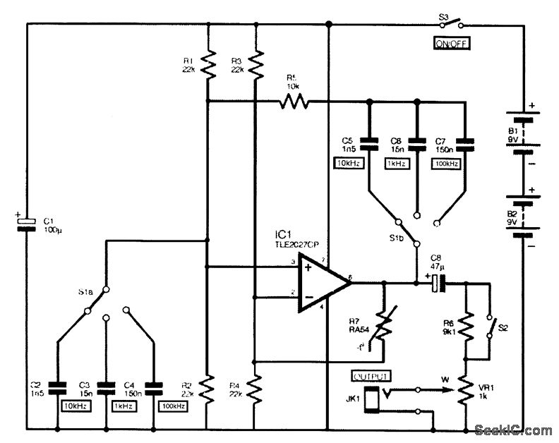
The complete circuit diagram for the audio sine-wave generator is presented. Resistors R1 and R2 provide biasing to the non-inverting (pin 3) input of IC1, and their parallel resistance constitutes one component of the Wien network. They correspond to...
The capacitor charges until the switching voltage is reached. When the switch (SUS) is activated, the inductor causes the current to oscillate. When the current through the switch drops below the holding current, the device turns off, and the...
The objective is to test a Wien bridge oscillator and ensure its proper functionality. There is a study of relevant material, but some concepts remain unclear. The Wien bridge oscillator is a type of electronic oscillator that generates sine waves....