
Piezo Buzzer driver
The basic buzzer driver circuit is designed to generate an audible tone by driving a piezoelectric buzzer. The circuit operates effectively within a voltage range of 3 to 28 volts DC, making it versatile for various applications, including alarms, notifications, and signaling devices. The output sound pressure level of 85 dBA at the resonance frequency of approximately 5 kHz ensures that the buzzer is loud enough for most environments.
The core components of the circuit typically include a transistor, which acts as a switch to control the power delivered to the buzzer. When a control signal is applied to the base of the transistor, it allows current to flow from the collector to the emitter, energizing the buzzer. The choice of transistor must accommodate the required current of 6 mA and the voltage range specified.
To achieve the desired resonance frequency, the circuit may incorporate passive components such as resistors and capacitors. These components can be arranged in an oscillator configuration to produce a square wave signal, which is essential for driving the piezoelectric buzzer at its optimal frequency. The selection of the capacitor value will influence the frequency of oscillation, enabling fine-tuning of the output tone.
In summary, this buzzer driver circuit is a straightforward yet effective solution for generating audible alerts, leveraging a combination of transistors and passive components to achieve the desired frequency and sound output. The design's flexibility in voltage operation makes it suitable for a wide range of electronic projects.This is a basic Buzzer driver circuit with resonance frequncy approximatly 5 Khz, 85 dBA. It operates on 3 to 28 v DC at 6mA. 🔗 External reference
Related Circuits
A voltage-controlled current source can be utilized to implement a laser diode driver. In comparison to switched (PWM) drivers, this simple linear laser diode driver offers distinct advantages. A voltage-controlled current source (VCCS) is a crucial component in driving laser...
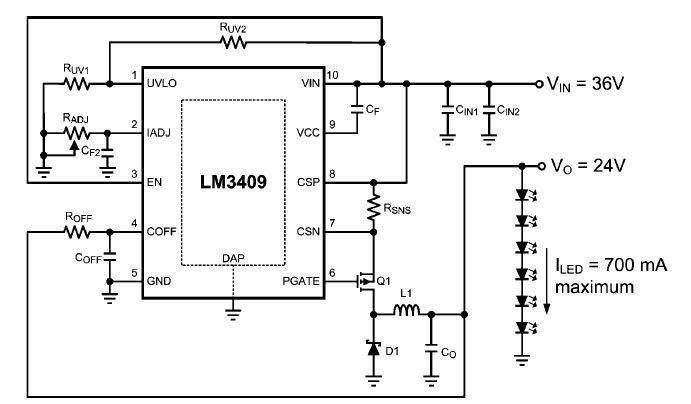
This dimming-controlled LED driver electronic circuit requires an input voltage of 36 volts and will provide an output voltage of 24 volts at a maximum current of 700 mA. The described dimming-controlled LED driver circuit is designed to efficiently convert...
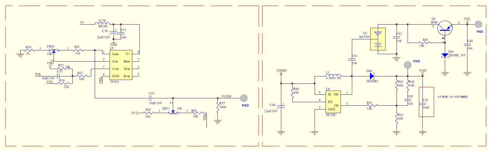
A circuit provided by an LCD manufacturer illustrates the use of the POL signal from the display to derive the VCOM signal. It has been noted that LCD Bias ICs typically generate VCOM from a high bias voltage. The...

This project involves controlling a small DC motor, sourced from an old personal cassette player, using the ATmega8 microcontroller. The ATmega8 features three PWM channels, of which two are utilized in this application. The PWM signals are sent to...
The artwork style of the operational amplifier and the meter face suggests that it is an ACC design from an old issue of ACC Notes. The second image was scanned, and the text below was written from scratch. If...
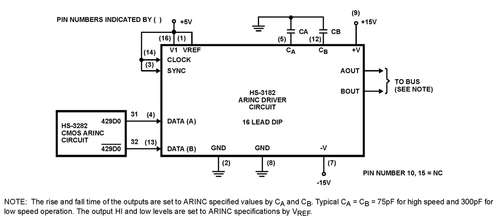
The HS-3182 is a monolithic dielectrically isolated bipolar differential line driver designed to meet the specifications of ARINC 429. This device is intended to be used with a companion chip, the HS-3282 CMOS ARINC Bus Interface Circuit, which provides...