
PWM Motor Driver with MOSFET H-Bridge and AVR ATmega8

This circuit utilizes the ATmega8 microcontroller, which is a popular choice for various embedded applications due to its versatility and ease of use. The microcontroller's PWM channels allow for precise control of the motor speed and direction, making it suitable for projects requiring fine motor control.
The H-bridge configuration, implemented with the RFD3055 MOSFETs, enables bidirectional control of the motor. By toggling the switch SW1, the circuit can switch between two states: one for forward motion and the other for reverse. The use of push-buttons S2 and S3 to control speed allows for straightforward user interaction, providing a simple interface to adjust the motor's performance.
In the schematic, the connections between the ATmega8 and the MOSFETs are critical for the operation of the motor. The PWM signals generated from the OC1A and OC1B pins are responsible for driving the gates of the MOSFETs, which in turn control the current flow through the motor. The choice of MOSFETs is essential, as they must be capable of handling the motor's current requirements while providing low on-resistance to minimize power loss.
Overall, this project exemplifies a basic yet effective implementation of motor control using a microcontroller, showcasing the integration of hardware components such as switches, buttons, and MOSFETs to achieve the desired functionality. The design can be expanded or modified for more complex applications, including feedback systems for speed regulation or remote control capabilities.Here is a very simple project of controlling a small DC-motor (taken from an old personal cassette player) with ATmega8. The ATmega8 is having three PWM channels, out of which two are used here. PWM waveforms are fed to MOSFET (RFD3055) H-bridge. Here, direction is controlled using a two-position toggle switch and speed of the motor is controlled by two push-buttons, one for increasing the speed and other for reducing.
The schematic is geiven here (click on the image to enlarge): When switch SW1 is closed, OC1A channel is active which will feed the PWM signal to Q1 & Q4 MOSFETs. The OC1B pin will remain low keeping the Q3 & Q2 in OFF condition. When SW1 is toggled to open position, OC1A pin will become low, making Q1 & Q4 OFF and OC1B will feed the PWM signal to Q3 & Q2, resulting in the change in the direction of current flow through motor.
Hence, motor rotation direction will change. The speed is controlled by Push-buttons S2 & S3. Pressing S2 will increase the speed in fixed steps. Similarly, pressing S3 will reduce the speed in fixed steps. 🔗 External reference
Related Circuits
The UTC H1277 is a semiconductor integrated Hall Effect Sensor integrated circuit (IC). It is designed for applications where the accurate tracking of small magnetic flux density changes is critical. The H1277 can be utilized in various applications, including...
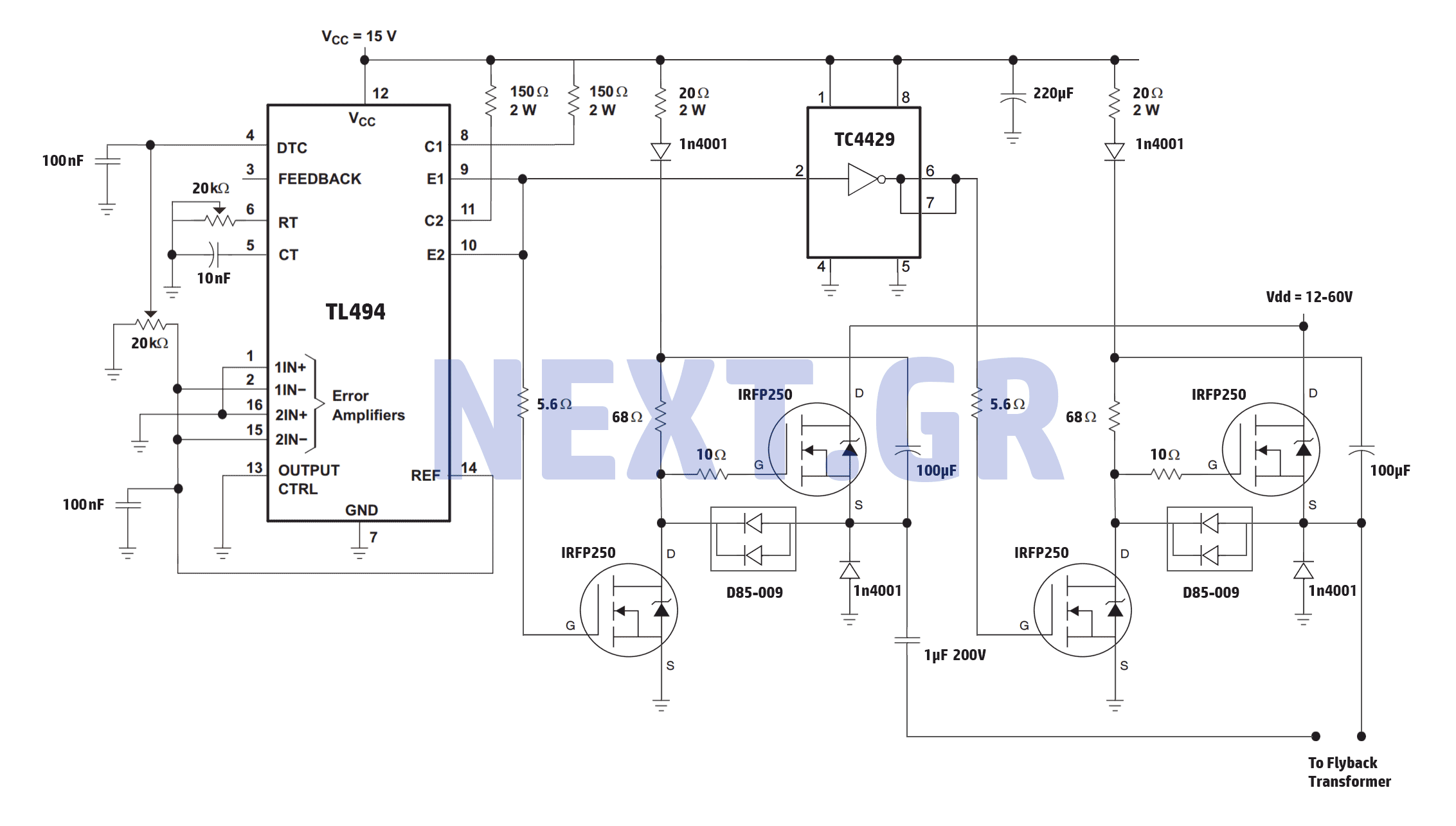
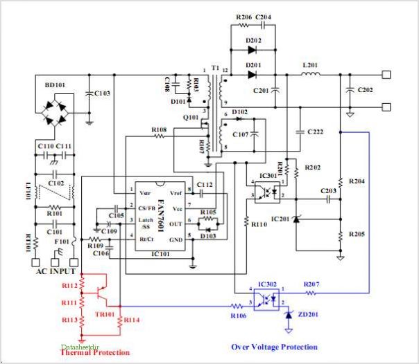
A reliable full bridge driver is essential for driving a flyback transformer. While many flyback driver schematics exist, most lack durability. The well-known Zero Voltage Switching (ZVS) driver, invented by Vladmiro Mazilli, is recognized for its reliability due to...
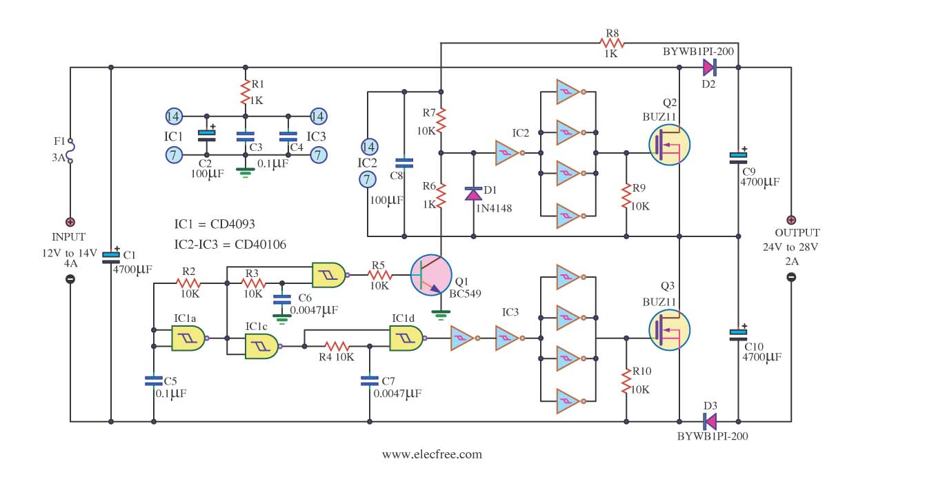
This is a DC to DC converter circuit designed to take an input of 12V to 24V at 4A and convert it to an output of 24V to 48V at 2A. The circuit utilizes simple components, including a CMOS...
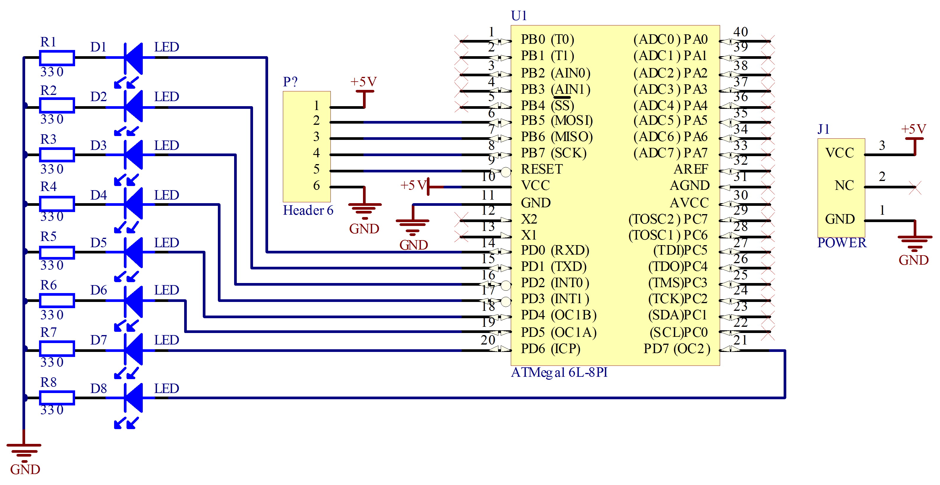
The project involves assembling a circuit that can be completed in 30 minutes. The required parts include: 1 circuit board, 1 Atmel AVR Atmega16 microcontroller, and 8 resistors with a value of 330 ohms each. The schematic for this project...
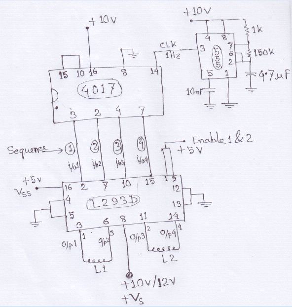
A stepper motor is to be rotated using a Johnson counter 4017 integrated circuit (IC). A bipolar stepper motor is utilized, with connections made from pins 3, 2, 4, and 7 of the 4017 IC following a specific sequence. The...
It was previously assumed that dynamic braking would be most effective at higher speeds. However, tests conducted with a Faulhaber (Micro Mo) gear motor demonstrated that the brake could hold the motor almost stationary. These gear motors are constructed...