
Piezoelectric Alarm Circuit
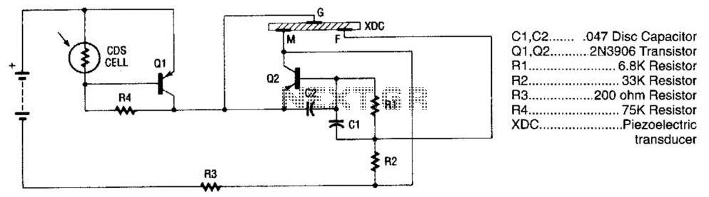
A CDS photo cell, constructed from cadmium sulfide, is a semiconductor that alters its resistance in response to light exposure. The greater the light intensity, the lower the resistance. This low resistance allows positive voltage to flow to the base of the PNP transistor Q1, keeping it turned off while light is incident on the CDS cell. Once the light is removed, the CDS cell's resistance exceeds 100 kΩ, which triggers Q1 to turn on. This action enables positive voltage to reach the emitter lead of Q2, initiating oscillation and causing the piezoelectric element (transducer) to generate a loud signal.
The circuit operates on a simple principle of light detection and sound generation. The CDS cell serves as a light sensor, influencing the state of transistor Q1, which in turn controls the oscillation of transistor Q2. This oscillation is crucial for driving the piezoelectric buzzer, which operates at a frequency of 3.137 kHz, producing a high-pitched sound that serves as the alarm signal. The design efficiently combines light-sensing and sound-generating components into a compact circuit, making it suitable for various applications where light presence detection is essential. The choice of a piezoelectric buzzer ensures that the alarm is both loud and effective, while the use of transistors allows for reliable switching and amplification of the signal. Overall, this circuit exemplifies a straightforward yet effective approach to creating an alarm system based on light detection. The alarm uses a fixed-frequency piezoelectric buzzer in conjunction with the cadmium-sulfide (CDS) cell and the two-transistor circuit to provide a unique effect. Whenever light reaches the CDS photo-electric cell, the alarm is silent. But when no light strikes the cell, transistor Ql turns on, and the circuit emits a high-pitched tone.The alarm consists of a piezoelectric disk that oscillates at the fixed frequency of 3.137 kHz, created by transistor Q2, capacitor CI and C2, and resistors Rl through R3.
Transistor Ql is used as a switch. It is forward-biased on by R4;-however, the CDS coll turns Ql off when the light is striking it. A CDS photo cell is made from cadmium sulfide, a semiconductor material that changes resistance when the light strikes it. The greater the amount of light, the lower the resistance. The low resistance conducts positive voltage to the base of pnp transistor Ql, keeping it turned off` when the light shines on the CDS cell.
As soon as the light is removed, the CDS cell provides a resistance of over 100 kQ. That causes Ql to turn on, allowing a positive voltage to reach the emitter lead of Q2, which then begins to oscillate. That then causes the piezoelectric element (transducer) to produce a loud signal. 🔗 External reference
Related Circuits
With the help of a simple ceramic piezoelectric detector, it is possible to assemble an interesting and useful impact sensor unit, which can be used to detect... An impact sensor unit utilizing a ceramic piezoelectric detector operates by converting mechanical...
A diode, such as the IN4148, has a typical temperature coefficient of -2 mV/°C at a 1 mA diode current. Transistors Q1 and Q2 form a constant current source. Diode D1 serves as the temperature sensor. Integrated circuits ICl-a...

This design circuit is a tachometer circuit based on the LM2907 integrated circuit, which can provide zero-crossing data to a digital system. At each zero crossing of the input signal, the charge pump alters the state of capacitor C1...
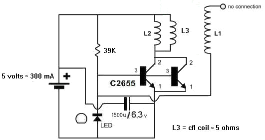
A 1N4148 diode and a 1-megohm resistor are included in the circuit. The inquiry pertains to how to power LED(s) using a 1.5-volt battery. There is also a question regarding the role of an additional coil, L3, and its...
The performance indices of the telecontrol receiving decoding circuit are as follows: radio frequency (f) = 27 MHz, audio frequency (f) = 5.5 kHz, 100% modulation in square-wave form; radio frequency deviation is ±600 Hz, and the frequency shift...
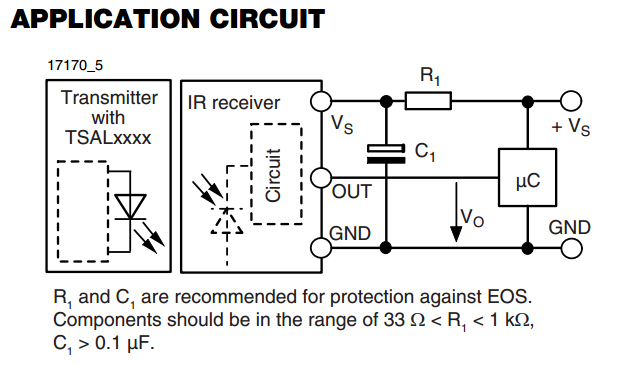
There is an interest in starting an introductory electronics project using an infrared (IR) sensor, but there is some confusion regarding the application circuit provided in the datasheet. The recommended resistor value is significantly lower than the calculated value....
Warning: include(partials/cookie-banner.php): Failed to open stream: Permission denied in /var/www/html/nextgr/view-circuit.php on line 713
Warning: include(): Failed opening 'partials/cookie-banner.php' for inclusion (include_path='.:/usr/share/php') in /var/www/html/nextgr/view-circuit.php on line 713