
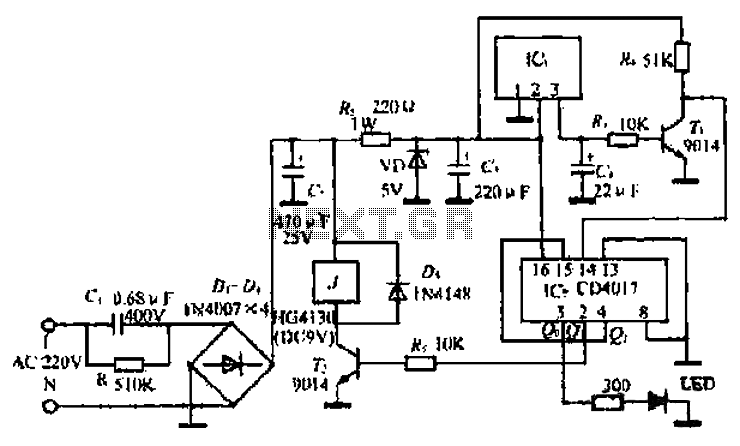
LM909 radio telecontrol receiving decoding circuit diagram
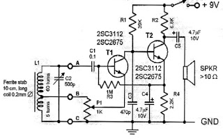
The telecontrol receiving decoding circuit is designed to operate at a radio frequency of 27 MHz, which is a common frequency for remote control applications. The audio frequency of 5.5 kHz indicates the frequency at which the audio signal is processed, allowing for effective communication between the transmitter and receiver. The circuit utilizes a square-wave modulation technique, achieving 100% modulation depth, which ensures that the transmitted signal maintains its integrity and is easily distinguishable from noise.
The circuit's frequency deviation of ±600 Hz indicates the range within which the carrier frequency can shift during operation, allowing for reliable signal detection. The use of frequency shift keying (FSK) at 160 Hz enables the transmission of binary data by shifting between two frequencies, which is essential for digital communication in telecontrol systems.
The duty factor, adjustable to 100%, 60%, or 30%, allows for variations in the on/off time of the transmitted signal, impacting the power consumption and responsiveness of the circuit. This flexibility is crucial for optimizing performance based on specific application requirements.
Transformers T1 and T2 play a vital role in the circuit's operation. T1, with a primary winding of 10 turns and a secondary winding of 4 turns, is likely used for impedance matching and signal coupling. The turns ratio of 2.5:1 suggests that the transformer steps down the voltage from the primary to the secondary side, which can be advantageous for interfacing with low-voltage circuits. T2, with a primary winding of 12 turns, serves a similar function, potentially providing additional signal conditioning or isolation.
Overall, the telecontrol receiving decoding circuit is engineered to ensure reliable communication and efficient signal processing, making it suitable for applications in remote control systems, wireless data transmission, and other related fields.The telecontrol receiving decoding circuit`s performance index shown as the chart are as follow: f radio frequency =27MHz, f audio frequency =5.5KHz, 100% modulation - square-wave; f radio frequency=±600Hz, and the frequency shift keying (FSK) is 160Hz, and the dutyfactor is 100%, 60% or 30%, T1`s primary is 10T, secondary is 4T; T2`s primary is 12T, second.. 🔗 External reference
Related Circuits
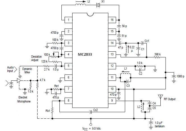
A simple FM transmitter circuit can be designed using the MC2833 integrated circuit, which is intended for cordless telephones and FM communication equipment. It features a microphone amplifier, a voltage-controlled oscillator, and two auxiliary transistors. The final output frequency...
This circuit is a simple one-transistor Audion type radio powered by a 1.5 V battery. It utilizes a pair of standard low-impedance headphones, wired in series to achieve a total impedance of 64 ohms. The power supply to the...
The ML4423 is an integrated controller designed for single-phase and two-phase AC induction motors. It features PWM (Pulse Width Modulation) capabilities for speed control and includes various protection circuits such as short circuit protection, fire protection, and a reference...
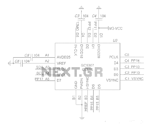
The system employs an optical fingerprint sensor utilizing the ARM Cortex M3 core, specifically the STMicroelectronics 32-bit high-performance microcontroller STM32F205RE. It incorporates a function body composition that utilizes the Sobel edge detection operator, Gabor filtering, image binarization, and various...
The DR-650 wiring diagram pertains to the Suzuki DR-650, a single-cylinder, dual-sport motorcycle. This wiring diagram includes a color code for the wires. The schematic diagram provides complete connections for various components, such as the speedometer, lights, CDI unit,...
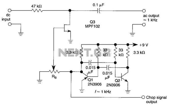
A JFET (MPF102) is utilized to chop a DC signal for amplification in an AC-coupled amplifier. Q3 serves as the chopper element, while Q1 and Q2 create a multivibrator to generate the chopping signal. Additionally, resistor Rr establishes the...
Warning: include(partials/cookie-banner.php): Failed to open stream: Permission denied in /var/www/html/nextgr/view-circuit.php on line 713
Warning: include(): Failed opening 'partials/cookie-banner.php' for inclusion (include_path='.:/usr/share/php') in /var/www/html/nextgr/view-circuit.php on line 713