
PIR Motion Sensor
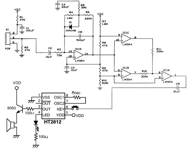
The PIR (Passive Infrared) motion sensor circuit is designed to detect motion based on changes in infrared radiation levels in the environment. This circuit typically consists of a PIR sensor module, which includes pyroelectric sensors that detect body heat. When a warm body, such as a human or animal, passes within the sensor's range, it triggers a change in the output voltage of the sensor.
The circuit is composed of the following key components:
1. **PIR Sensor**: The core component responsible for detecting motion. It contains two pyroelectric elements that generate a voltage when exposed to infrared radiation. The sensor has a specific detection angle and range, usually around 120 degrees and up to 10 meters, respectively.
2. **Operational Amplifier (Op-Amp)**: An op-amp is used to amplify the weak signal generated by the PIR sensor. This amplification is crucial for ensuring that the output signal is strong enough to trigger subsequent components in the circuit.
3. **Resistors and Capacitors**: These passive components are used to set the gain of the op-amp and to filter the output signal. They help stabilize the circuit and prevent noise from affecting the performance.
4. **Output Stage**: The output from the op-amp can be connected to various devices, such as a relay for activating alarms, lights, or other electronic devices. This output stage may include additional components like transistors to handle higher current loads.
5. **Power Supply**: The circuit requires a stable power supply, typically 5V to 12V, depending on the specifications of the PIR sensor and other components used.
The design emphasizes simplicity and high efficiency, making it suitable for various applications, including security systems, automatic lighting, and energy-saving solutions. The integration of operational amplifiers enhances the circuit's capability to accurately detect motion and minimize false alarms, thereby improving overall performance.The following circuit shows about PIR Motion Sensor Circuit Diagram. Features: simple and high efficiency, operational amplifiers a sound .. 🔗 External reference
Related Circuits
The UHF motion detector operates on the Doppler radar principle. An oscillating signal is generated by the oscillator (Q1), and a portion of this energy is reflected back. The UHF motion detector employs the Doppler radar principle to detect motion...

The robot requires a method for detecting obstacles (or other robots) without making physical contact. This capability allows the robot to determine whether to avoid or confront and investigate the obstacle based on its programming. This document outlines the...

The LMP91200 is a configurable sensor analog front-end (AFE) designed for managing low-power analytical sensing applications, specifically for 2-electrode sensors. This device offers all the necessary functionality to detect changes based on a delta voltage from the sensor. It...
This presence detector or proximity sensor circuit responds to the presence of any conductive object, including humans. The sensitivity can be adjusted with potentiometer P1, which is positioned at a considerable distance from the rest of the circuit. This...
This circuit is a motion detection sensor that utilizes a light source and a detector in the form of an infrared motion detector. The motion sensor employs an infrared LED and a phototransistor. The sensitivity of the sensor can...
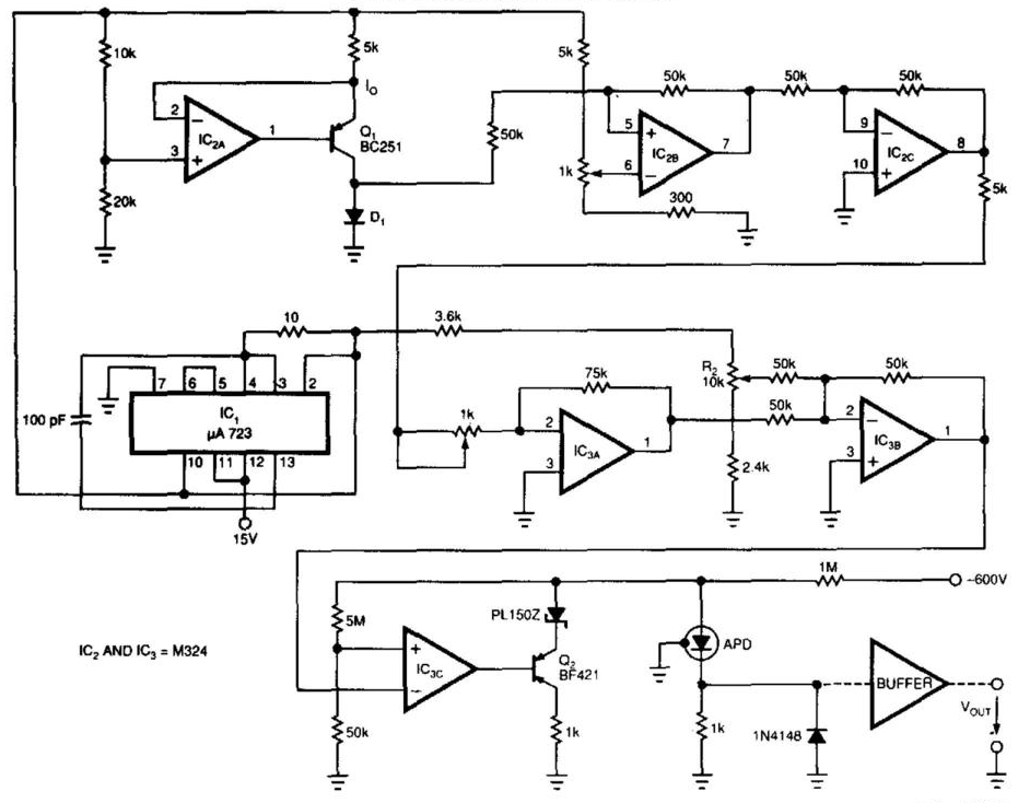
Laser-receiver circuits must bias their avalanche photodiodes (APD) to achieve optimal gain. Unfortunately, an APD's gain depends on the operating temperature. The circuit controls the operating voltage of an APD over a large temperature range to maintain the gain...