
obstacle detection sensor circuit

The described obstacle detection circuit employs ultrasonic technology to facilitate non-contact sensing capabilities in robotic applications. The choice of a 555 timer in astable mode for generating a 40 kHz signal is critical, as this frequency is optimal for ultrasonic transmission and reception, allowing for effective detection of obstacles at varying distances. The inclusion of a potentiometer for frequency adjustment provides flexibility in tuning the system to account for environmental factors and specific application requirements.
The use of the LM358N op-amp in the receiving circuit enhances the sensitivity of the detection system, with the non-inverting amplifier configuration allowing for amplification of the received ultrasonic signal. The subsequent low-pass filter ensures that the output voltage is smoothed, reducing noise and providing a cleaner DC signal for further processing.
The comparator configuration in U2b is essential for establishing a threshold level that determines when an obstacle is detected. By adjusting the sensitivity via the potentiometer VR2, the system can be calibrated to respond to different types of obstacles or varying signal conditions, enhancing its versatility.
The integration of the 2N2222 transistor as an inverter allows for simple interfacing with the Handy Board's logic levels, facilitating seamless communication between the detection circuit and the robot's control system. The LED indicator serves as a visual confirmation of obstacle detection, providing immediate feedback for debugging and operational verification.
Overall, this circuit design effectively combines ultrasonic sensing technology with robust signal processing techniques, enabling reliable obstacle detection in robotic systems.The robot requires means of detecting an obstacle (or another robot) without making physical contact. This allows the robot to decide whether to avoid or to confront and investigate the obstacle depending on its programming.
This is one solution and the design of obstacle detection circuit. Here`s the figure of the circuit; In this circuit, ultras onic transducers were chosen for this because they are more reliable and have a greater range than IR sensors (effectiveness of IR sensors varies with ambient light level). The IC U1 is a 555 timer in astable configuration to oscillate at 40 KHz. Instead of using exact values for the two resistors that is placed between pin 6 and 7, a 10K ohm potentiometer (VR1) was used.
This also allows for some fine tuning of the output frequency. The output (pin 3) is then attached to a 40 KHz ultrasonic transmitter (UTR1). The receiving circuit is a dual LM358N (U2) op-amp. An ultrasonic receiver (UTR2) is connected to pin 3, the non-inverting input of U2a which is a non-inverting amplifier with a gain of 220. The output of U2a is put through a low pass filter via D1, C3 and R4 to produce a somewhat stable DC voltage.
This DC voltage is fed into the non-inverting input of U2b configured as a non-inverting comparator. Sensitivity of U2b is controlled by VR2 to set the threshold trigger value. The output of U2b is connected through R5 to the base of a bipolar 2N2222 transistor (Q1) acting as an inverter with a LED (LED1) to indicate if an obstacle has been detected. Finally, the collector of Q1 goes to the Handy Board`s digital port (Handy Board uses inverted logic levels, 0V is a logic 1 and +5V is a logic 0).
🔗 External reference
Related Circuits
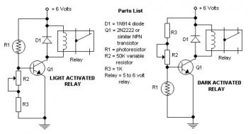
The potentiometer adjusts the trigger level. The diode in the circuit diagram is specified as 1N914, which is suitable for light-duty relays; however, since the 1N914 is a signal diode, it is not ideal for this application. A 1N4001...
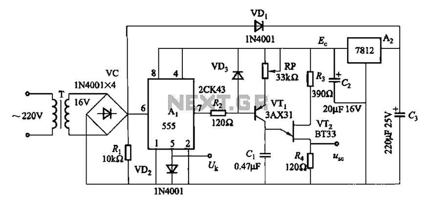
Both circuits can synchronize trapezoidal wave voltage, which is converted into intermittent small rectangular pulses. Its working principle involves periodic operation in synchronization with the grid frequency of the zero-volt switching voltage of the DC chopper. Due to the...
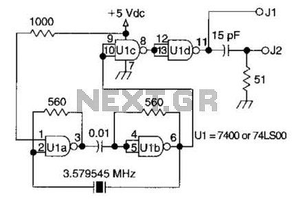
A circuit utilizing one 7400 TTL can operate with fundamental type crystals ranging from 1 to approximately 13 MHz. The output is rich in harmonics, making this oscillator suitable for calibration and testing applications. The circuit in question employs a...
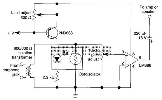
An optoisolator is utilized as an attenuator in this circuit. When the LM386 draws more current from audio signals, the 2N3638 activates, which biases the optoisolator on, thereby reducing the volume. The circuit employs an optoisolator to achieve signal attenuation,...
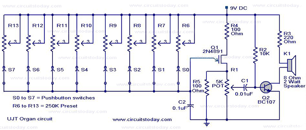
A UJT organ circuit with a circuit diagram is explained in detail. A 2N4891 UJT is used for the operation of the circuit. The UJT (Uni-Junction Transistor) organ circuit is designed to utilize the unique characteristics of the 2N4891 UJT...
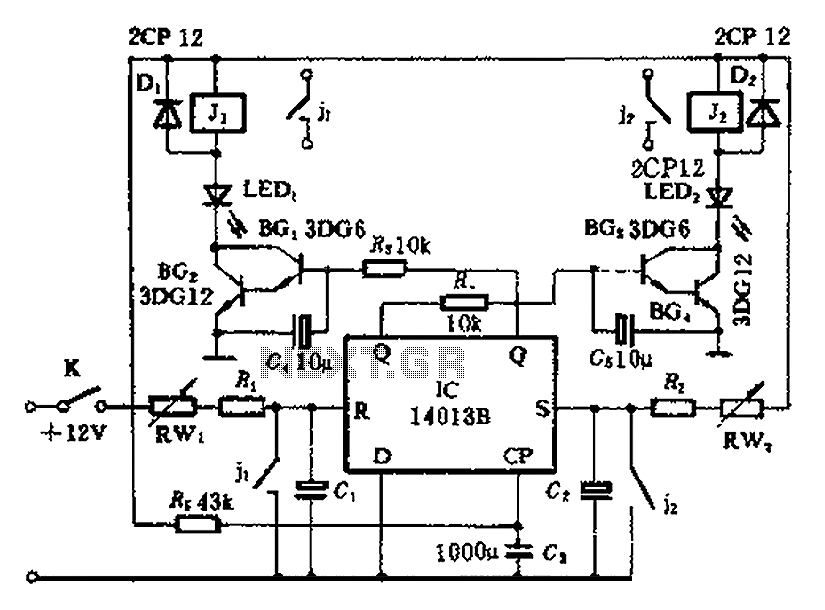
The timing control circuit is a sequential circuit that allows for sequential timed control of two switches. The control time can be adjusted from a few seconds to several tens of seconds. If mechanical control is applied for reciprocating...
Warning: include(partials/cookie-banner.php): Failed to open stream: Permission denied in /var/www/html/nextgr/view-circuit.php on line 713
Warning: include(): Failed opening 'partials/cookie-banner.php' for inclusion (include_path='.:/usr/share/php') in /var/www/html/nextgr/view-circuit.php on line 713