
Simple Thermocouple Amplifier circuit
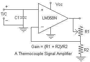
The circuit incorporates the LM358N dual operational amplifier, which is configured to amplify the low-level millivolt signal produced by the thermocouple (TC). The gain of the amplifier is set by the resistor values R1 and R2 in a non-inverting configuration, where R1 is connected from the output to the inverting input, and R2 is connected from the inverting input to ground. The selected resistor values of 100KΩ for R1 and 1KΩ for R2 result in a gain of approximately 100, allowing the output voltage to scale appropriately from the TC's maximum output of 40 mV to a practical range of 0 to 4VDC.
The circuit is powered by a 6V battery, ensuring that the LM358N operates within its recommended voltage range. The operational amplifier draws about 1.0 mA, making it suitable for battery-powered applications. To mitigate noise and interference, particularly during transient conditions such as motor startup, a bypass capacitor (C1) of 0.1 µF is placed across the power supply pins of the op-amp. This capacitor helps filter high-frequency noise that could affect the stability of the output signal.
Polarity is crucial in this setup; incorrect wiring of the thermocouple can lead to misleading outputs. If the TC is connected in reverse, the output may drop significantly, potentially mimicking a valid low-temperature reading. To address this issue, an alternative design could include an offset voltage to ensure that the output remains at a minimum of 1.0VDC when the TC is reversed, thus providing a clear indication of incorrect wiring. The upper output limit can then be adjusted to 5VDC, enhancing the circuit's robustness and usability in practical applications.Continuing with the thermocouple interface concept, the next step is to amplify the TC's millivolt signal into a more readable analog voltage, on the order of 0 to 5VDC. This simple circuit fits the bill. The LM358N is a dual op-amp IC. I'm quite sure any op-amp IC would do fine, just be sure it can accept a Vcc which is compatible with your battery pack.
The IC draws ~ 1.0 mA. The resistors form a feedback loop into the op-amp, with a gain described in the schematic, and based upon the resistances R1 and R2. I used 100K and 1K respectively for the breadboarding, delivering a gain of roughly 100. This works well with the TC's range of up to 40 mV, with the output then being from 0 to 4VDC.
I was surprised to find the circuit as stable as it was. Wired to a 6V battery, I attached a speed 300 motor simulating the starter motor to the same V+ and ground. Initial spooling of the starter motor caused a small hiccup in the signal, but it quickly restabilized, and it shouldn't cause any problems in operation.
The C1 (0.1 uF ceramic) is essential to minimize this interference. The polarity of the thermocouple is important. If wired backwards, the circuit drops low and stays there, and could be confused with an operating TC at room temperature. A more elegant solution would be to offset the output so that if wired backwards, the output would deliver 1.0VDC, with the upper limit now 5VDC rather than 4.
🔗 External reference
Related Circuits
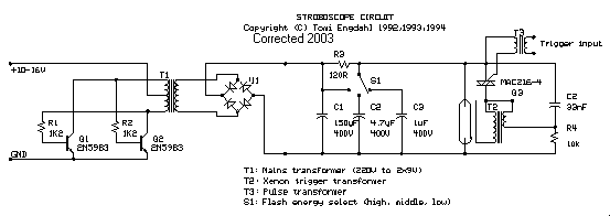
The stroboscope tube requires approximately 250-400V DC for operation. This high voltage is generated by a simple voltage step-up circuit constructed from transistors Q1, Q2, and transformer T1. This circuit outputs about 230V AC, which is then rectified by...
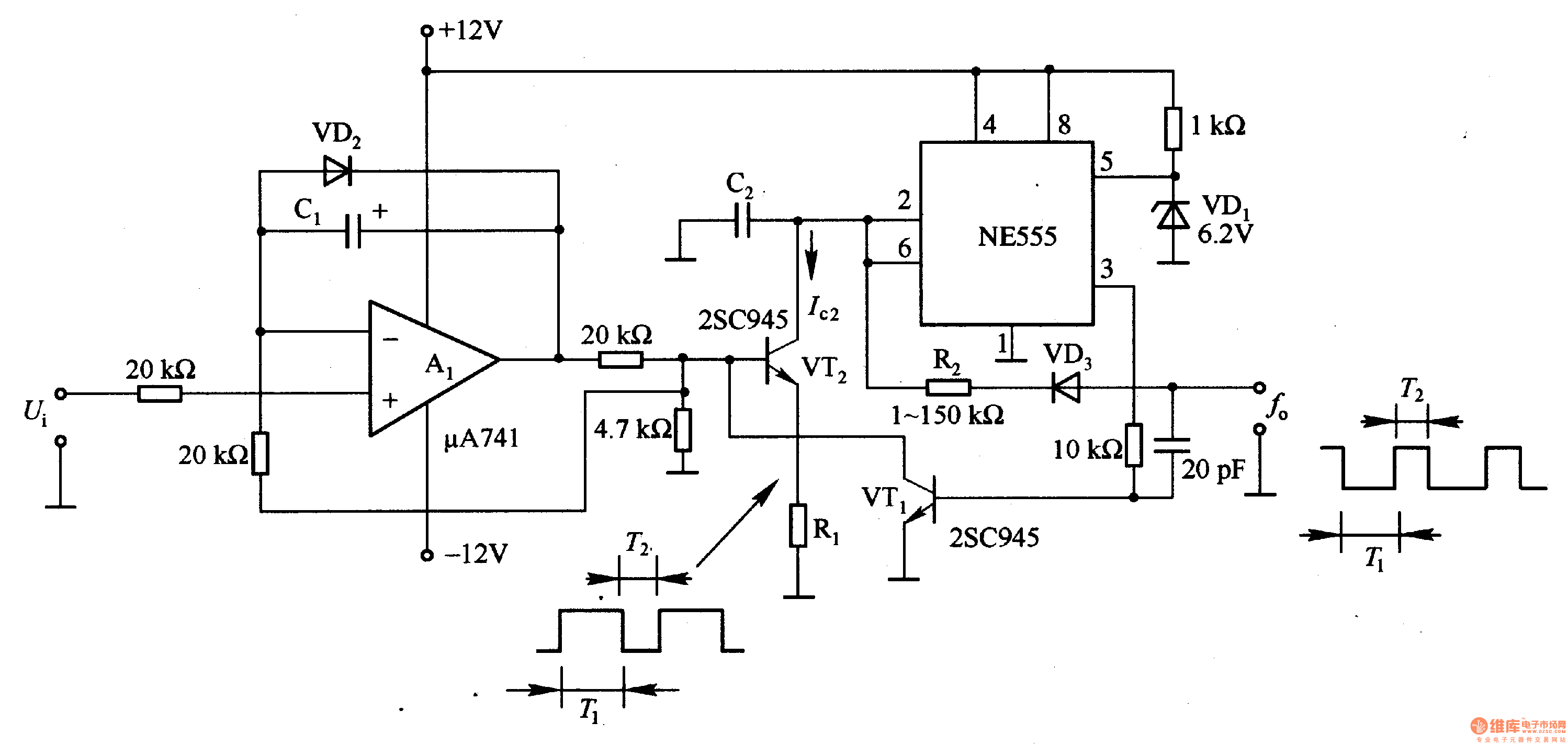
In the circuit, the oscillation frequency of the NE555 is controlled by VT2. When the output at pin 3 is low (during the T1 period), VT1 stops conducting, and VT2 begins to conduct with a current Ic2 flowing through...
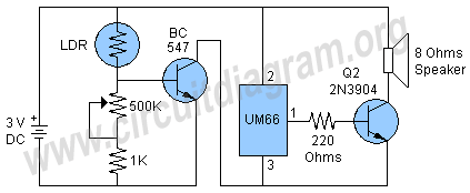
This project involves a light-activated alarm or morning alarm circuit that produces a pleasant melody upon detecting light. To use this circuit as a morning alarm, it should be placed in a location that receives morning sunlight. A 500K...
Determining whether a battery is empty or if there is a fault with a device can be challenging when a battery-powered device, such as a Walkman, fails to power on. Before seeking professional repair, it is advisable to test...

This circuit is activated when switch SW1 is pressed, grounding the base of transistor Q2. The pulse rate is approximately equal to 0.7 multiplied by the product of resistor R3 and capacitor C1. The described circuit features a transistor Q2,...
this is a very easy circuit to build - all parts can be found at the local electronics shop. The described circuit is characterized by its simplicity and accessibility, making it an ideal project for beginners or those looking to...