
Energy Saving Night Light circuit
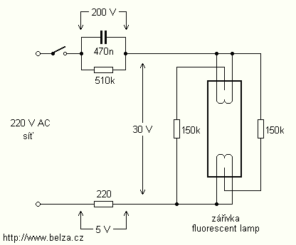
The circuit described involves the use of fluorescent lamps functioning as a ballast or electronic ballast inverter. This design utilizes capacitors to reduce voltage reactance, which is critical in managing the electrical characteristics of the circuit. The ignition process for the auxiliary electrodes is facilitated by the inclusion of resistors with a resistance of approximately 150 Ohms. The operational procedure indicates that only one resistor is necessary to initiate the lamp, although this may result in longer blinking periods before stable operation is achieved. Notably, the design omits the use of a filament, which is typically employed in traditional fluorescent lamps, and instead, the filament connections are short-circuited.
The circuit is designed for relatively low-voltage fluorescent tubes, making it suitable for operation with battery power. This is advantageous for portable applications where power supply constraints exist. The drive circuit must be capable of handling a considerable supply voltage to ensure the fluorescent lamps function effectively.
In the context of the capacitors used within this circuit, two examples are provided: one capacitor has a capacitance of 430 nF rated for 200 V, while the other has a capacitance of 470 nF rated for 250 V. It is essential that the capacitors are rated for at least AC 250 V or DC 400 V to ensure reliable operation and longevity. The durability of capacitors in this application is a critical consideration, as aged or degraded capacitors can lead to failure, potentially resulting in short circuits and subsequent damage to the entire system. Regular monitoring and replacement of these components may be necessary to maintain circuit integrity and performance. The lamps are usually used as ballast or electronic ballast inverter. Here it is used to reduce voltage capacitor reactance. Interesting is also the method of ignition of the auxiliary electrodes involved over 150 Ohm resistors. To start simply involve only one, but the lamp is switched on for longer blinks. Filament is not used and are short-circuited. The operation is relatively low-voltage fluorescent tubes, it looks like it worked pretty well and easy to drive on battery power.
The drive would only have to load a relatively large supply voltage, or fluorescent lights. In a fluorescent lamp had capacity of 430 nF capacitor and the voltage was only 200 V. The second had a capacity of 470 nF and a voltage of 250 V. In any case, the capacitor should be at AC 250 V or 400 V DC at least I wonder how long used Capacitors can withstand before it breaks or shorted out and burns down the entire system? 🔗 External reference
Related Circuits
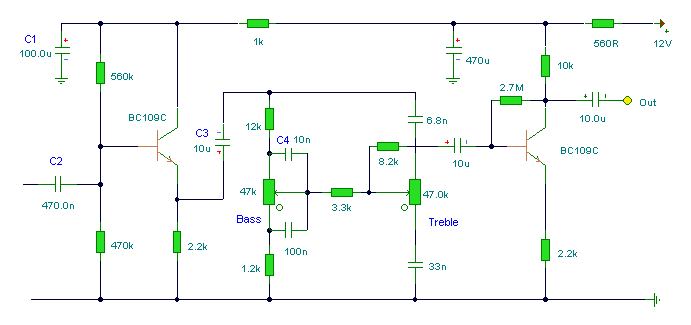
The first BC109C transistor (on the left side) functions as a buffer, offering the circuit a high input impedance of approximately 250k ohms and a voltage gain slightly less than unity. As the Baxandall tone control circuit is a...
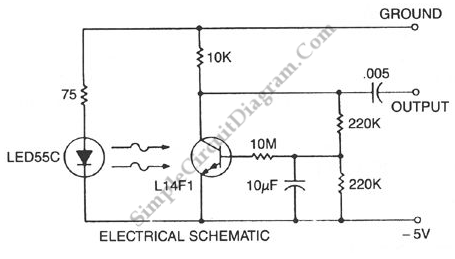
This circuit is a Low-Light Level Drop Detector. It utilizes a self-biasing configuration to detect small changes in light levels. The Low-Light Level Drop Detector circuit is designed to sense minute variations in ambient light conditions, making it suitable for...
The circuit for a car wiper speed controller allows for adjustable wiper speed, ranging from one to ten cycles per second. This feature enables flexibility in operation and contributes to energy efficiency. The car wiper speed controller circuit typically employs...

This design circuit is for audio graphic equalizers, which are commonly found as commercial products, yet published circuits for them are quite rare. The circuit features a simple design that requires an operational amplifier (op-amp) to amplify the input...
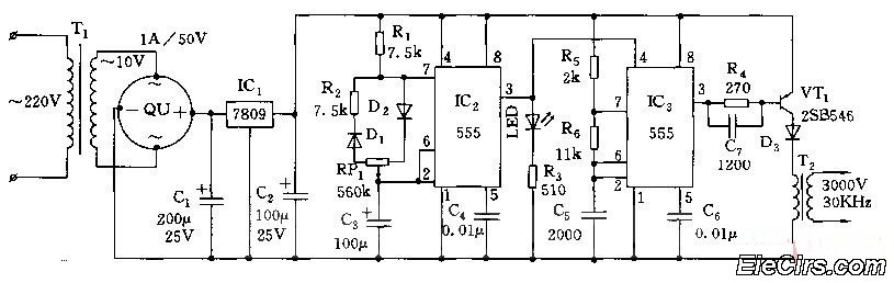
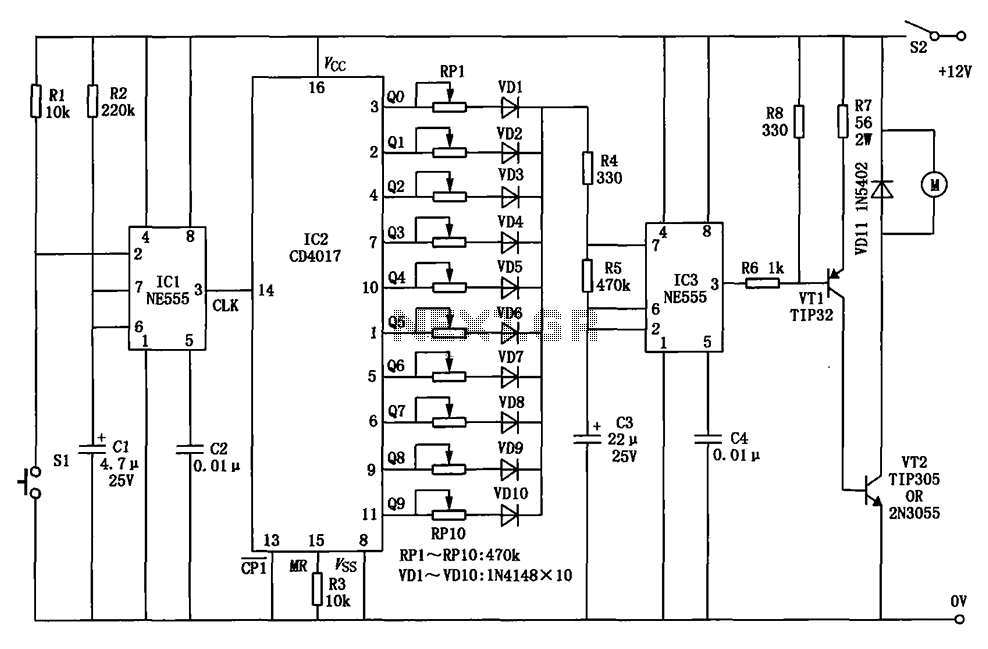
Adjust the RP1 to modify the pulse duty cycle of IC2, which in turn alters the pulse oscillation time of IC3. This regulation allows for the control of ozone generation time, effectively changing the concentration of ozone in the...

An audio power amplifier circuit for a 3-watt stereo amplifier using the MAX 7910 IC is explained below. The audio power amplifier circuit utilizing the MAX 7910 IC is designed to deliver a maximum output power of 3 watts per...
Warning: include(partials/cookie-banner.php): Failed to open stream: Permission denied in /var/www/html/nextgr/view-circuit.php on line 713
Warning: include(): Failed opening 'partials/cookie-banner.php' for inclusion (include_path='.:/usr/share/php') in /var/www/html/nextgr/view-circuit.php on line 713