
Alc (Automatic Level Control) Circuit
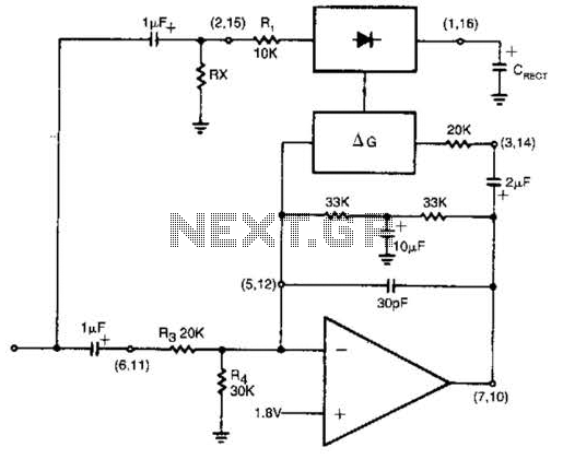
The described circuit functions as a specialized rectifier with a feedback mechanism that ensures a consistent output level despite variations in input signal strength. The core principle of this design relies on the inverse relationship between input level and gain. Specifically, when the input signal decreases, the gain compensates by increasing, thereby stabilizing the output.
The rectifier component receives the input signal, which can vary significantly within the specified range. The circuit is engineered to maintain a fixed output of 1 dB, regardless of whether the input signal is at its maximum of +14 dB or its minimum of -43 dB. This feature is particularly beneficial in applications requiring stable output levels, such as audio processing or signal conditioning.
Incorporating additional external components allows for fine-tuning of the output level, providing flexibility in adapting the circuit to different operational needs. These components may include variable resistors, capacitors, or operational amplifiers, which can be configured to modify the gain characteristics or output response of the circuit.
Overall, this design exemplifies a robust solution for applications where consistent output is crucial, and the ability to adjust output levels adds versatility to the circuit's functionality. The rectifier input is tied to the input. This makes gain inversely proportional to input level so that a 20-dB drop in input level will produce a 20-dB increase in gain. The output will remain fixed at a constant level. The circuit will maintain an output level of 1 dB for an input range of +14 to -43 dB at 1 kHz. Additional external components will allow the output-level to be adjusted. 🔗 External reference
Related Circuits

A VU (Volume Unit) meter has traditionally been a key component of audio metering systems. The Peak Program Meter (PPM) is known for its inadequacy in accurately displaying peak signal levels. This circuit serves the same function as previously...
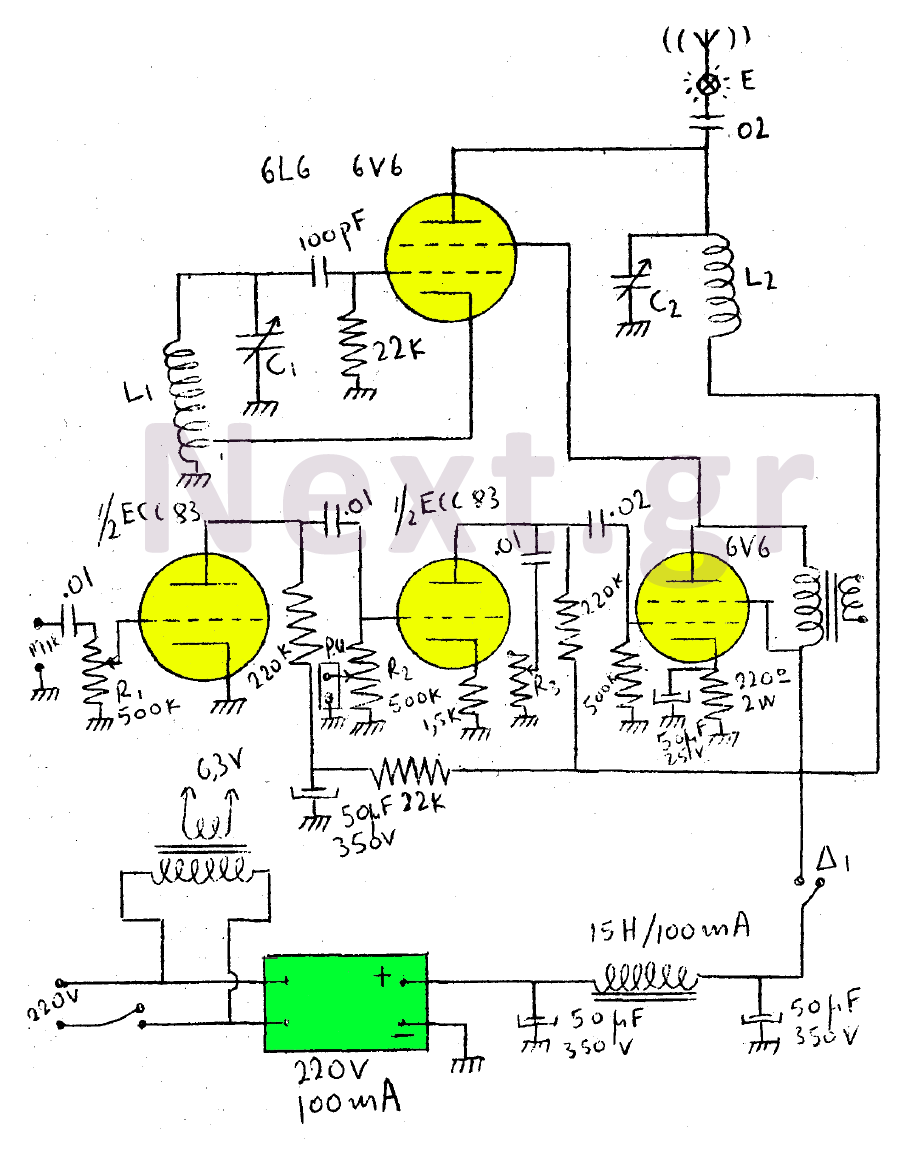
This circuit features a wearer assembly that includes a single lamp, either a 6V6 or 6L6, functioning as both an oscillator and an output amplifier. Coil L1 serves as the medium wave oscillation coil, while coil L2 is composed...
This sensitive FM radio tuner is an ideal circuit for hobbyists who wish to construct their own tuners rather than purchasing a pre-assembled product. The FM radio tuner circuit is designed to receive frequency modulation signals, providing a clear and...
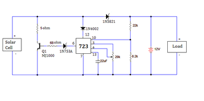
The ultimate source of energy is the Sun. It is possible to generate current from sunlight using solar panels. These panels convert light energy into electrical energy. A solar panel consists of a number of solar cells, which produce...
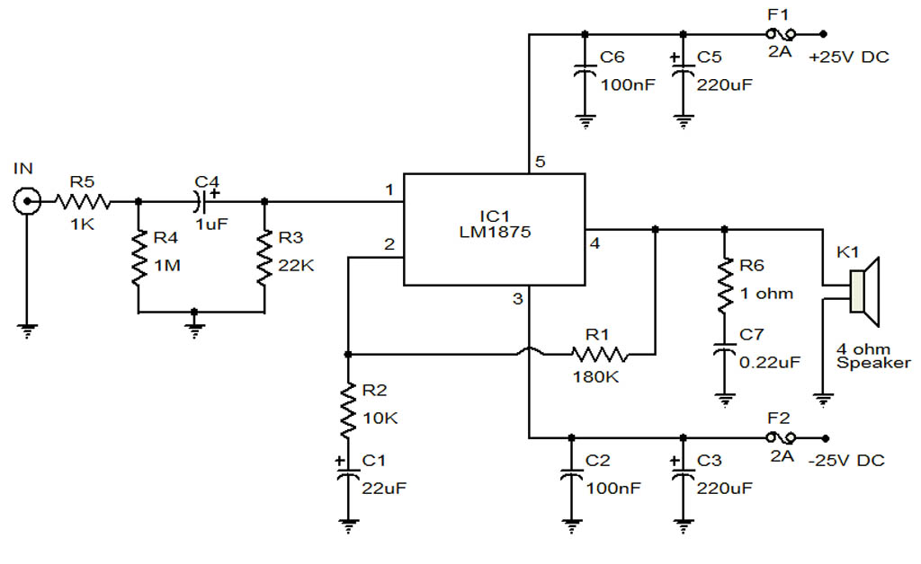
The circuit illustrates a 20-Watt audio amplifier diagram based on the LM1875 integrated circuit (IC). It is designed for use in automotive applications and provides an output power of 20 Watts. The 20-Watt audio amplifier circuit utilizing the LM1875 IC...
The SE555/NE555 timer was first introduced by Signetics Corporation around 1971. The pin connections and their functions are as follows: Pin 1 (Ground) is the most-negative supply potential and is typically connected to circuit common when powered by positive...
Warning: include(partials/cookie-banner.php): Failed to open stream: Permission denied in /var/www/html/nextgr/view-circuit.php on line 713
Warning: include(): Failed opening 'partials/cookie-banner.php' for inclusion (include_path='.:/usr/share/php') in /var/www/html/nextgr/view-circuit.php on line 713