
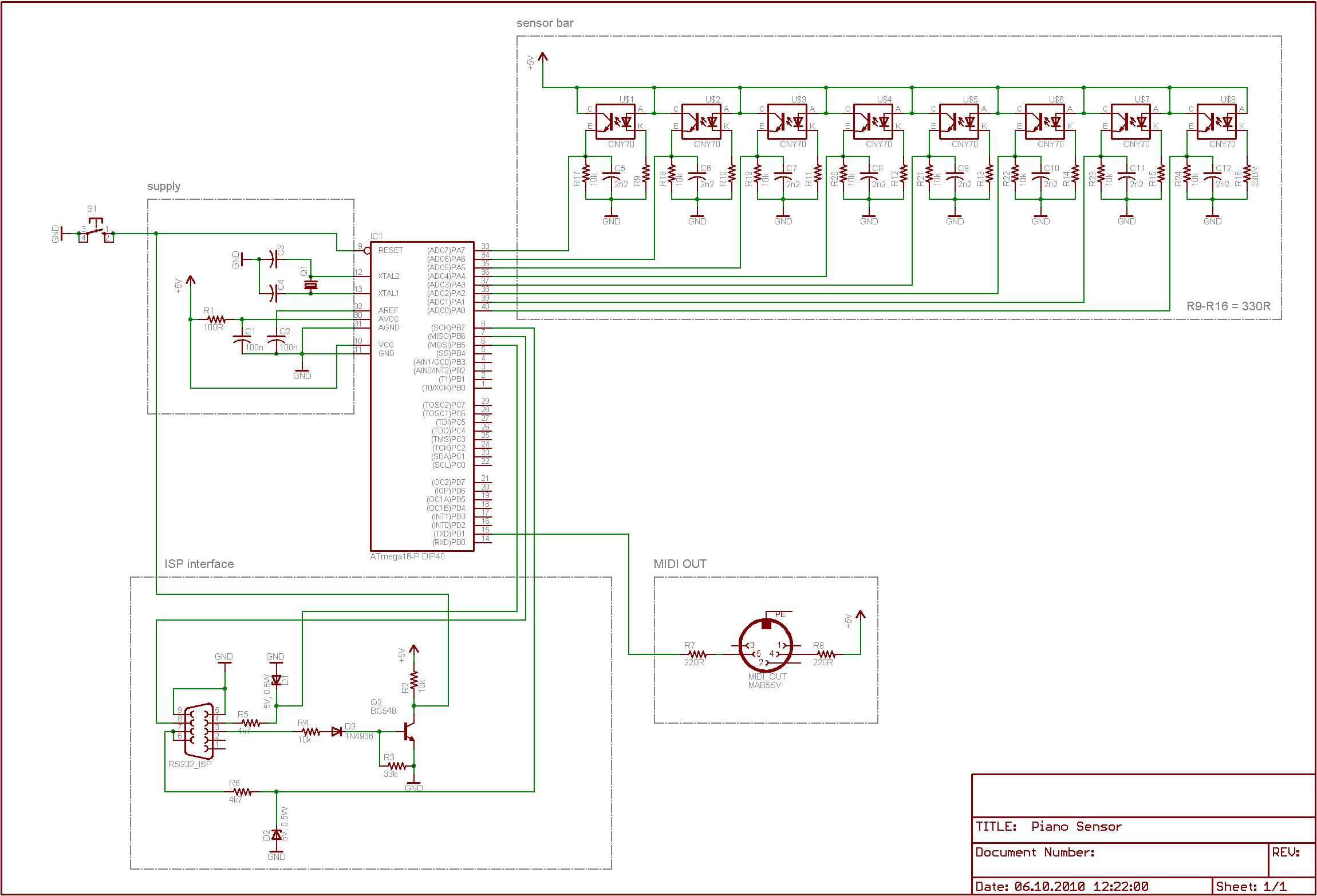
Playing piano with optical sensors
To improve the responsiveness of an electronic keyboard, a systematic approach can be adopted that involves both hardware and software modifications. The keyboard's sensitivity can be influenced by several factors, including the type of switches used, the debounce time in the circuitry, and the software algorithms that interpret keystrokes.
1. **Switch Selection**: The choice of switches is critical. Mechanical switches, for example, often provide better tactile feedback and faster actuation times compared to membrane switches. The actuation point of the switch should be measured, as lower actuation points can lead to quicker responses.
2. **Debounce Circuitry**: In electronic keyboards, debounce time is the period during which the keyboard ignores additional inputs after a key is pressed to prevent multiple signals from being sent. Measuring the current debounce time and optimizing it can significantly improve responsiveness. This can be achieved through the use of hardware debouncing techniques, such as RC (resistor-capacitor) filters, or through software methods that implement algorithms to filter out noise from the key press signals.
3. **Microcontroller and Firmware**: The microcontroller used in the keyboard should be capable of processing input signals at high speeds. The firmware running on the microcontroller should be optimized to handle keystroke detection efficiently. This includes minimizing the latency in reading key states and processing them to send data to the host device.
4. **Signal Path Optimization**: Ensuring that the signal path from the switch to the microcontroller is as short and direct as possible can reduce delays. This may involve re-evaluating the PCB layout to minimize trace lengths and using high-quality components that do not introduce significant delays.
5. **Testing and Measurement**: The measurement of the fastest keystroke should include both the physical actuation time and the time taken for the signal to be processed and sent to the host. This can be done using high-speed oscilloscopes or specialized testing equipment that can capture the timing of the keystrokes accurately.
By addressing these factors, the overall responsiveness of the electronic keyboard can be significantly improved, resulting in a more satisfying user experience.trying to improve the responsiveness of an electric keyboard. He was unsatisfied with the lack of adequate sensitivity to keystroke. The first step in his process was to measure how fast the quickest keystroke actually is.. 🔗 External reference
Related Circuits
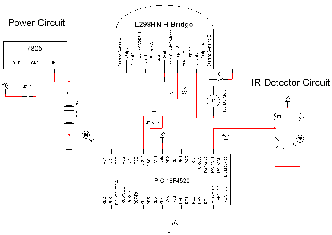
The simple motor optical encoder circuit is not particularly difficult; however, it requires careful verification to ensure all connections are correct before initial operation. The primary components utilized in the circuit include the 7805 voltage regulator, the PIC18F4520 microcontroller,...
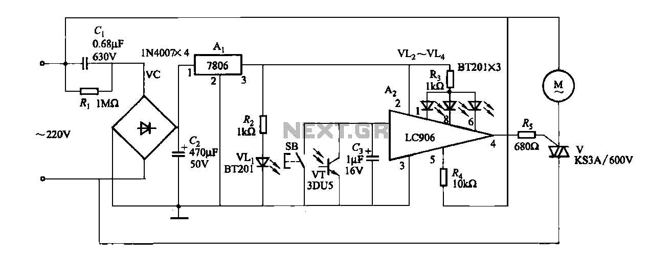
The ceiling fan speed control circuit depicted in Figure 3-6 utilizes a capacitor step-down method and a three-terminal fixed 7806 voltage regulator. It achieves fan speed control through the integrated circuit A2, which regulates the conduction angle of the...
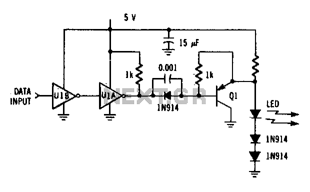
The driver circuit utilizes an MC74LS04 and a discrete transistor. The circuit is capable of driving the LED (MFOE12QO) at data rates of up to 1 Mbps. The driver circuit employs the MC74LS04, which is a hex inverter, to provide...
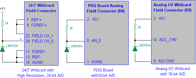
Interfacing the LM335A temperature sensor with A/D converters involves measuring temperature using the LM35 and LM335A sensors alongside the 9S12 HCS12 microcontroller. This process includes analyzing both calibrated and uncalibrated temperature errors of integrated circuit temperature sensors. The LM335A is...
This optical trigger is a general-purpose module designed for use with standard 3mm package infrared diode emitters and corresponding matched phototransistors. The emitter terminal on the module sources approximately 27mA to ground with a 1.2V drop across the diode....
By attaching a standoff to the center of a 2-inch, 8-ohm speaker, it can be transformed into a vibration sensor with a natural resonance below 100Hz, which is quite effective. The implementation involves hanging the speaker from the lid...